Headliner Cooling System

a cooling system and headliner technology, applied in the field of heat transfer and cooling systems, can solve the problems of drowning victims in exceptionally cold water, tens of minutes without oxygen, and critical time,

Inactive Publication Date: 2014-02-13
WELKINS
View PDF3 Cites 17 Cited by
  • Summary
  • Abstract
  • Description
  • Claims
  • Application Information

AI Technical Summary

Benefits of technology

[0007]It is therefore an object of the present invention to protect a patient's brain from further damage from a moment of injury until and during brain injury therapy.

Problems solved by technology

In treating and successfully recovering from head injury, time is critical.
In particular, when brain cells die, the associated function provided by those brain cells is more apt to be lost by the patient.
In particular, drowning victims in exceptionally cold water have in some cases been submerged and deprived of oxygen for tens of minutes.

Method used


Image

  • Headliner Cooling System
  • Headliner Cooling System
  • Headliner Cooling System

Examples


Embodiment Construction

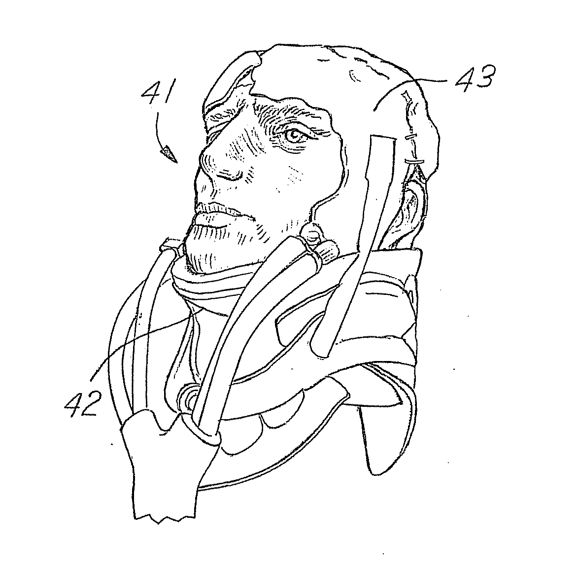
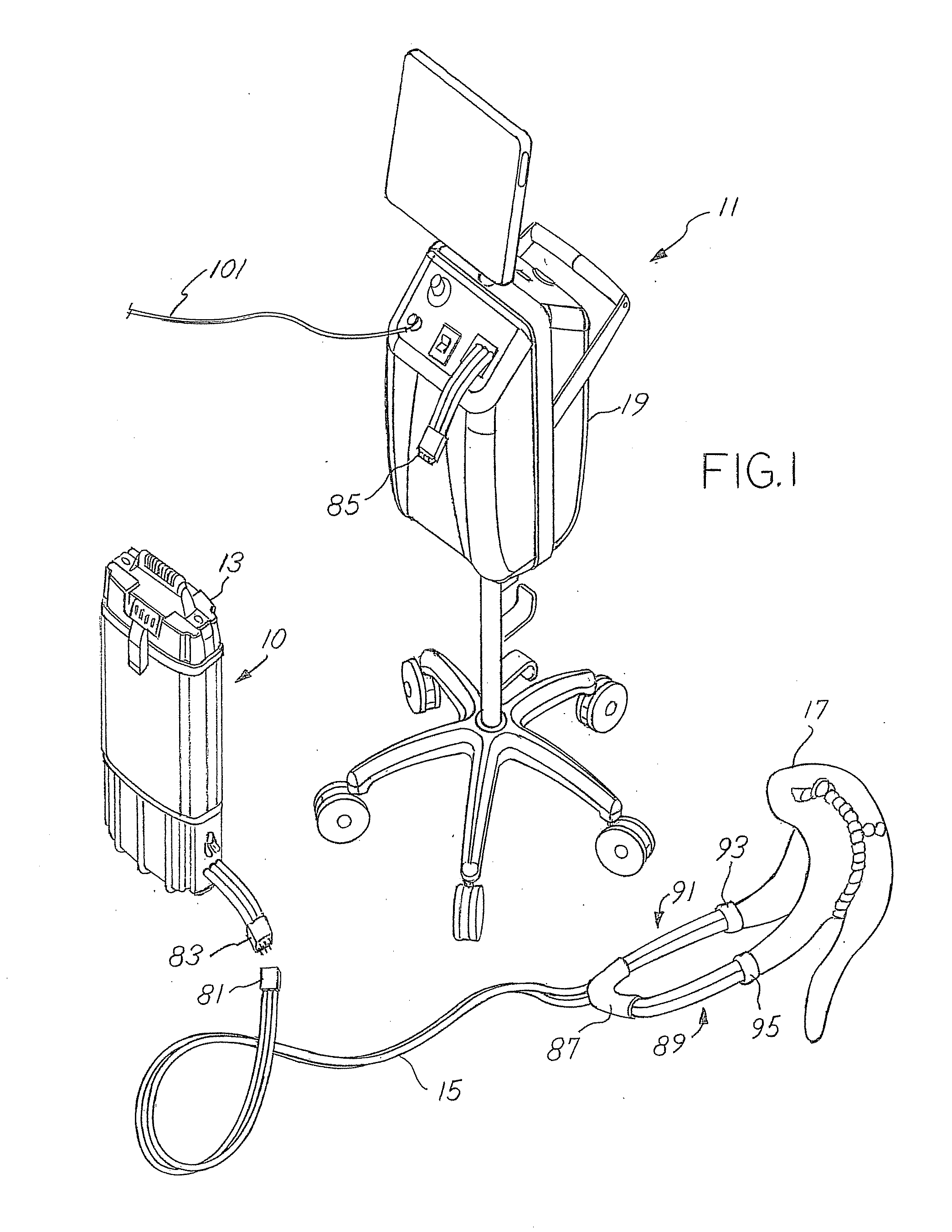
[0030]Referring to FIG. 1, two separate cooling systems 10 and 11 are shown. Cooling system 10 includes an EMT conditioning unit 13 (“Emergency Medical Team” conditioning unit), an umbilical tubing 15 and a body-conformal heat exchanger 17. Cooling system 11 includes an ICU conditioning unit 19 (“Intensive Care Unit” conditioning unit), umbilical tubing 15 and body conformal heat exchanger 17. In one embodiment, the EMT unit 13 may be constructed for ease of transport to a location where the patient has a need, for example, a medical emergency. The EMT unit and patient are transported to an intensive care facility where the ICU conditioning unit 19 is located and there used to continue the therapy; the EMT unit is disconnected from tubing 15 and the ICU unit is attached to the same tubing 15. In other embodiments, the EMT unit 13 may be used in other applications such as home use, athletic side line cooling, etc.

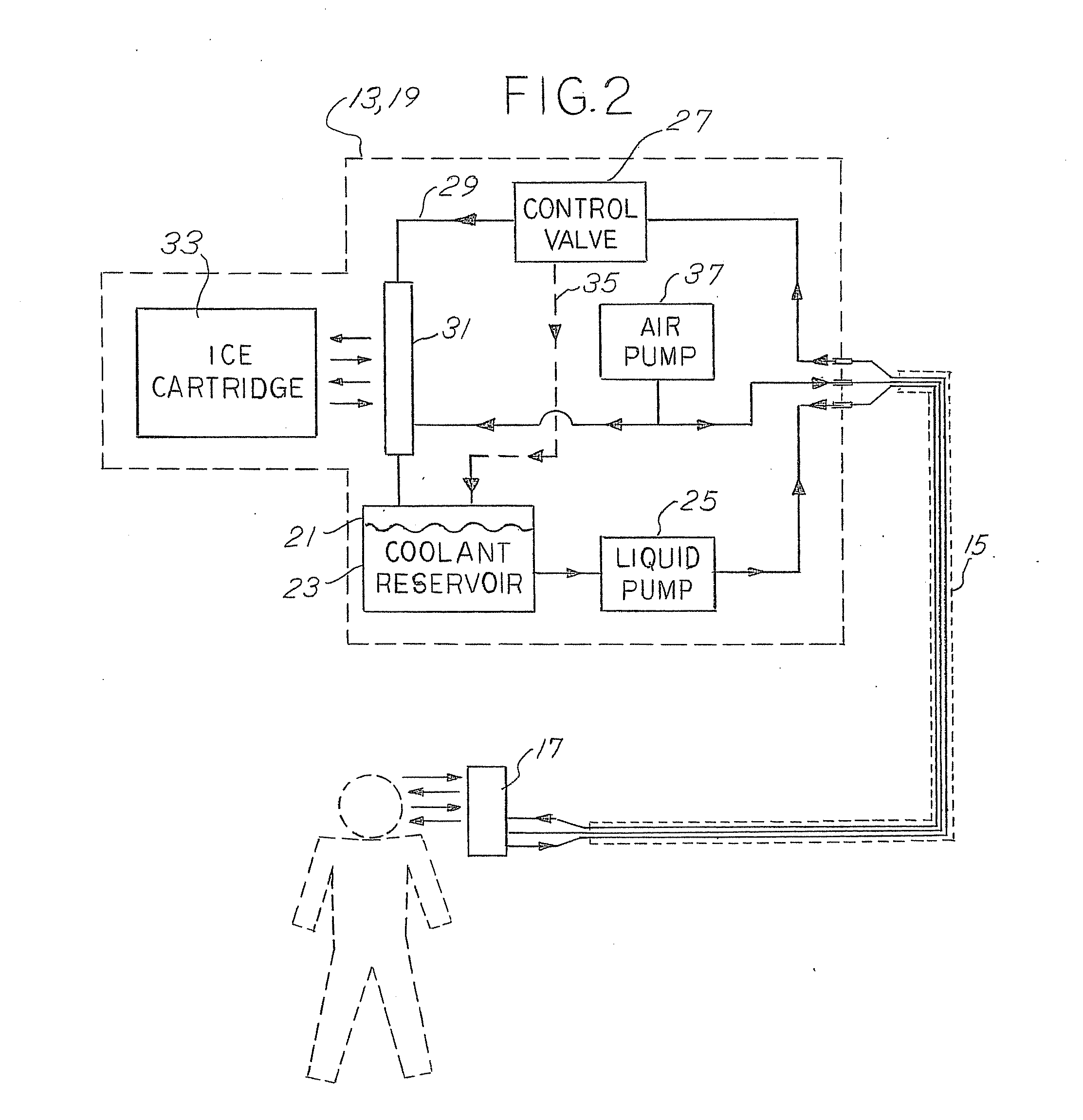
[0031]Operation of cooling systems 11, 13 is illustrated in FIG. 2. Bot...


PUM


Abstract

A cooling system for cooling a portion of an individual's body via a body-conformed apparatus. The cooling system includes a unit remote from the body and tethered to the body conformed apparatus. A replaceable ice cartridge is disposed in the unit and relative to a coolant pathway that circulates coolant to and from the individual. A control valve within the coolant pathway is operable to control the amount of coolant passing the ice cartridge and thus control the temperature of the coolant leaving the unit.

Description

RELATED APPLICATIONS[0001]This application claims priority to, U.S. Provisional Patent Application No. 61 / 681,505 having a filing date of Aug. 9, 2012, which is incorporated herein by reference, in its entirety.FEDERALLY SPONSORED RESEARCH OR DEVELOPMENT[0002]This invention was made with government support under DoD Contract HQ003410-C-0031 awarded by the Department of Defense and administered by WHS ACQUISITION & PROCUREMENT OFFICE for the Joint IED Defeat Organization (JIE DDO). The contract gives the government certain rights in the invention. However, the government later terminated the contract.MICROFICHE / COPYRIGHT REFERENCE[0003][Not Applicable]BACKGROUND OF THE INVENTION[0004]The invention relates to heat transfer and cooling systems for cooling a portion of an individual's body via a body-conformed apparatus, and more particularly relates to a method and device for controlling the amount of temperature change caused to the portion of the individual's body for treating in sit...

Claims


Application Information

Patent Timeline
Patent Type & Authority Applications(United States)
IPC IPC(8): A61F7/00
CPCA61F7/00A61F7/0085A61F7/02A61F2007/0009A61F2007/0018A61F2007/0056A61F2007/0091A61F2007/0093A61F2007/0096A61F2007/0225A61F2007/0231A61F2007/108
Inventor ELKINS, WILLIAMJORDAN, JR., THEODORE MAURICEMOORE, CHRISTOPHER CROCKETTBLODGETT, CHRISTOPHER
Owner WELKINS
Why Eureka
Try Eureka