Vacuum transfer element and method for transferring tubular labels

a technology of vacuum transfer and tubular labels, which is applied in the directions of lamination, labelling of short rigid containers, lifting devices, etc., to achieve the effect of simple and low cos

Active Publication Date: 2014-02-20
SIDEL SPA
View PDF6 Cites 6 Cited by
  • Summary
  • Abstract
  • Description
  • Claims
  • Application Information

AI Technical Summary

Benefits of technology

[0027]It is an object of the present invention to provide a vacuum transfer element for transferring a tubular label, which allows to overcome the above need in a straightforward and low-cost manner.

Problems solved by technology

Because the labels are fed through the heating device still in contact with a supporting surface of the conveyor device, known labeling machine of the above type have several drawbacks, mainly due to not allowing selective control of the position of the labels along the articles, and as such as are fairly inflexible.

Method used


Image

  • Vacuum transfer element and method for transferring tubular labels
  • Vacuum transfer element and method for transferring tubular labels
  • Vacuum transfer element and method for transferring tubular labels

Examples


Embodiment Construction

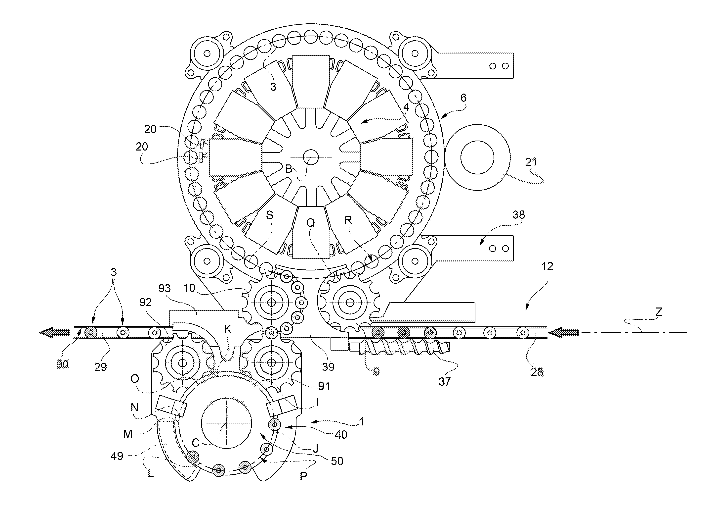
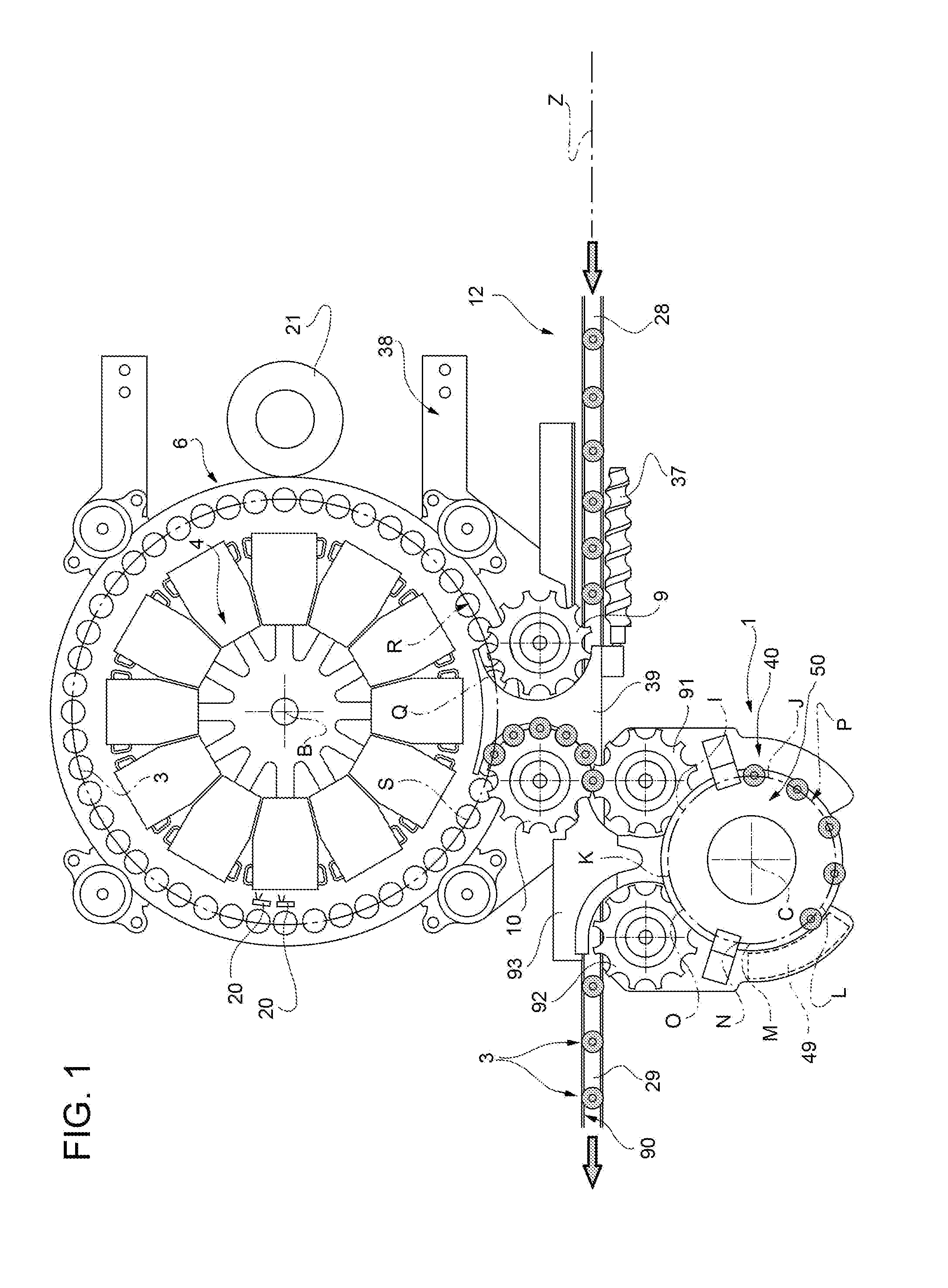
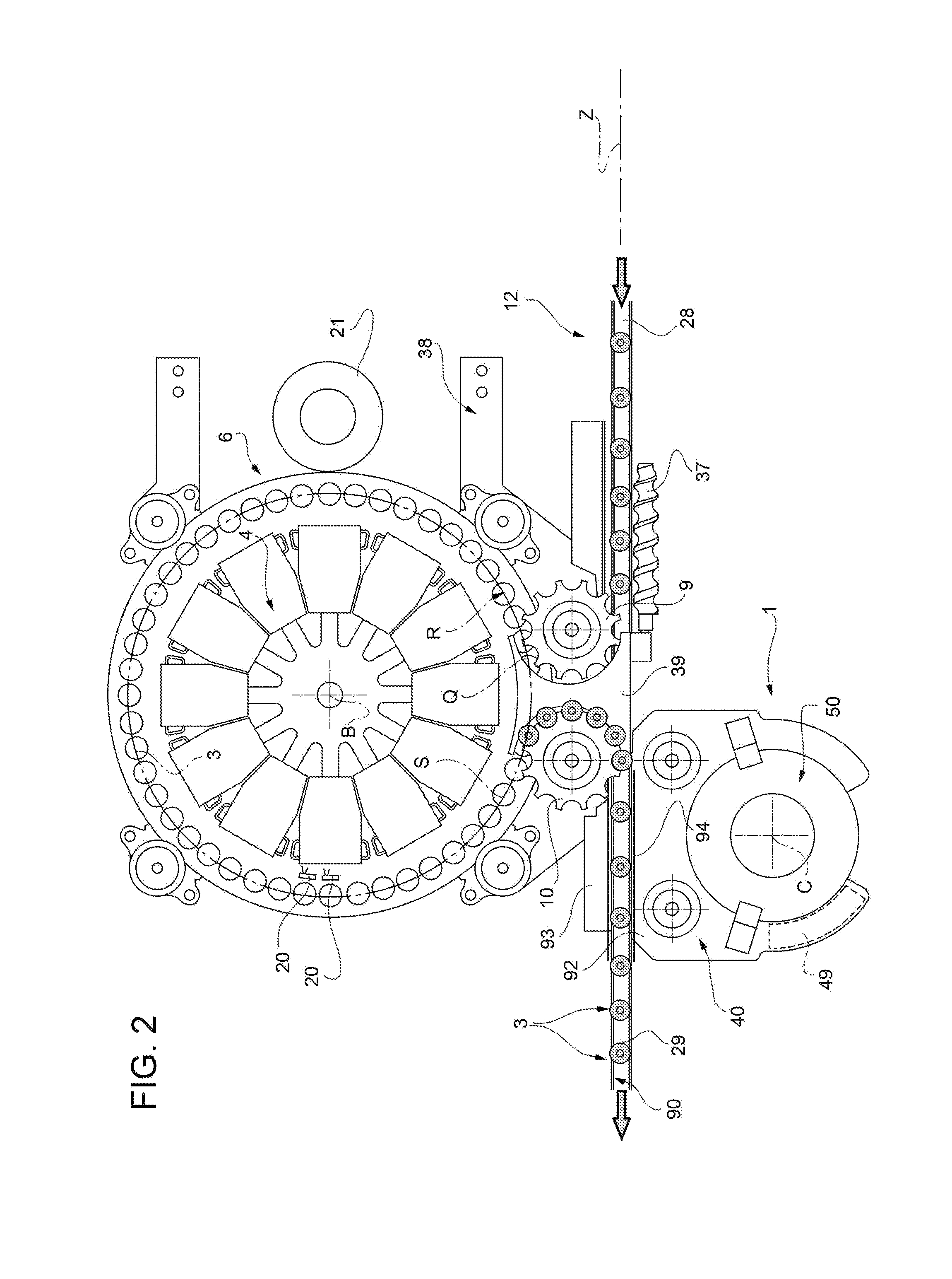
[0036]With reference to the FIGS. 1 to 5, number 1 indicates as a whole a module for the application of a plurality of tubular labels 2 of heat-shrinkable material to respective articles 3, in particulars containers or bottle filled with a pourable liquid food product.

[0037]Module 1 is adapted to be incorporated into a labeling machine 6 (FIGS. 6 and 7).

[0038]In detail, labeling machine 6 applies labels 2 onto relative articles 3 in a first position while module 1 is adapted to move, if necessary, labels 2 relative to articles 3 from the first to a second position.

[0039]In the embodiment shown, the second position of labels 2 is raised relative to the first position of labels 2.

[0040]Very briefly, tubular labels 2 (commonly called “sleeve labels”) are formed by labeling machine 6 through the steps of (FIGS. 6 and 7):

[0041]cutting a web unwound from a supply roll into a plurality of flat rectangular or square label 7 of a heat-shrinkable material;

[0042]bending each label 7 in a cylin...


PUM

PropertyMeasurementUnit
vacuum transferaaaaaaaaaa
vacuumaaaaaaaaaa
pressureaaaaaaaaaa

Abstract

There is described a vacuum transfer element for transferring a tubular label having a first axis (A) form a first to a second position, comprising a first surface which may reciprocate along a second axis (E) parallel to first axis (A), comprises a plurality of ports and is adapted to cooperate with an outer side, opposite to first axis (A), of said tubular label; first ports are selectively connectable to a vacuum source to establish a vacuum suction action on outer side, at least when first surface moves from first to second position; surface is angularly fixed relative to said second axis (E); first surface is angularly fixed relative to second axis (E).

Description

TECHNICAL FIELD [0001]The present invention relates to a vacuum transfer element and to a method for transferring a tubular label.BACKGROUND ART [0002]As it is generally known, labeling machines are used to apply labels to containers or articles of all sort. Typically used with beverage bottles or vessels are tubular labels (commonly called “sleeve labels”), which are obtained by:[0003]cutting the web unwound from a supply roll into a plurality of rectangular or square labels of a heat-shrinkable material;[0004]bending each label in a cylindrical configuration such that the opposite vertical edges overlap one another; and[0005]welding the overlapped edges of each cylindrical label.[0006]In particular, a labeling machine is known comprising a carousel mounted to rotate about a substantially vertical first longitudinal axis, and having a number of carrier units, each for feeding a respective article between an input station, where the articles are fed onto the conveyor wheel, and an o...

Claims


Application Information

Patent Timeline
Patent Type & Authority Applications(United States)
IPC IPC(8): B65C3/14B65C9/08
CPCB65C9/08B65C3/14B65C3/065B65C9/1819B65C9/1826B65C9/1823
Inventor GIULIANI, MATTIAROSSI, MIRKOMOLINARI, STEFANOBOCCHI, ANDREAPIAZZA, GASTON
Owner SIDEL SPA
Why Eureka
Try Eureka