Novel multi-level converter topology with the possibility of dynamically connecting individual modules in series and in parallel

a converter topology and multi-level technology, applied in the direction of power conversion systems, instruments, electrical equipment, etc., can solve the problems of irreparable damage, unfavourable duty cycles, complex configuration of converters,

Active Publication Date: 2014-02-20
TECH UNIV MUNCHEN
View PDF5 Cites 90 Cited by
  • Summary
  • Abstract
  • Description
  • Claims
  • Application Information

AI Technical Summary

Benefits of technology

[0054]Two-quadrant modules have the disadvantage of limited functionality, but they enable the use of fewer switching elements and may represent an advantageous choice according to the intended application.

Problems solved by technology

However, these converter configurations become more and more complex as voltages increase, because the voltages must be distributed uniformly to the series-connected semiconductors and corresponding protection measures are needed to prevent overvoltages in the individual semiconductors.
In the event of a malfunction, extremely high discharge currents can flow through the capacitor in the intermediate circuit, and these in turn can lead to irreparable damage as a result of powerful mechanical forces and / or flashover damage.
A further disadvantage consists in that variable voltages can only be generated with drives of such kind with the aid of corresponding PWM conversion duty cycles, so that large voltage differences result in unfavourable duty cycles.
But this represents a large unused potential.
Particularly in application fields in which a relatively large voltage ratio is to be generated between the input and the output, or where low voltages occasionally have to be absorbed or released with high currents, this leads to unfavourable switching states and relatively high power losses in the components concerned.
Consequently, the individual modules and their energy stores are not used to the best effect in these applications either.
However, this high price does not appear to be practical except for research applications.

Method used


Image

  • Novel multi-level converter topology with the possibility of dynamically connecting individual modules in series and in parallel
  • Novel multi-level converter topology with the possibility of dynamically connecting individual modules in series and in parallel
  • Novel multi-level converter topology with the possibility of dynamically connecting individual modules in series and in parallel

Examples


Embodiment Construction

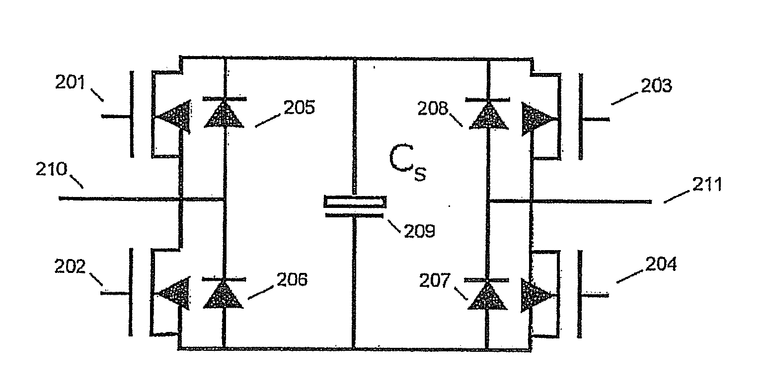
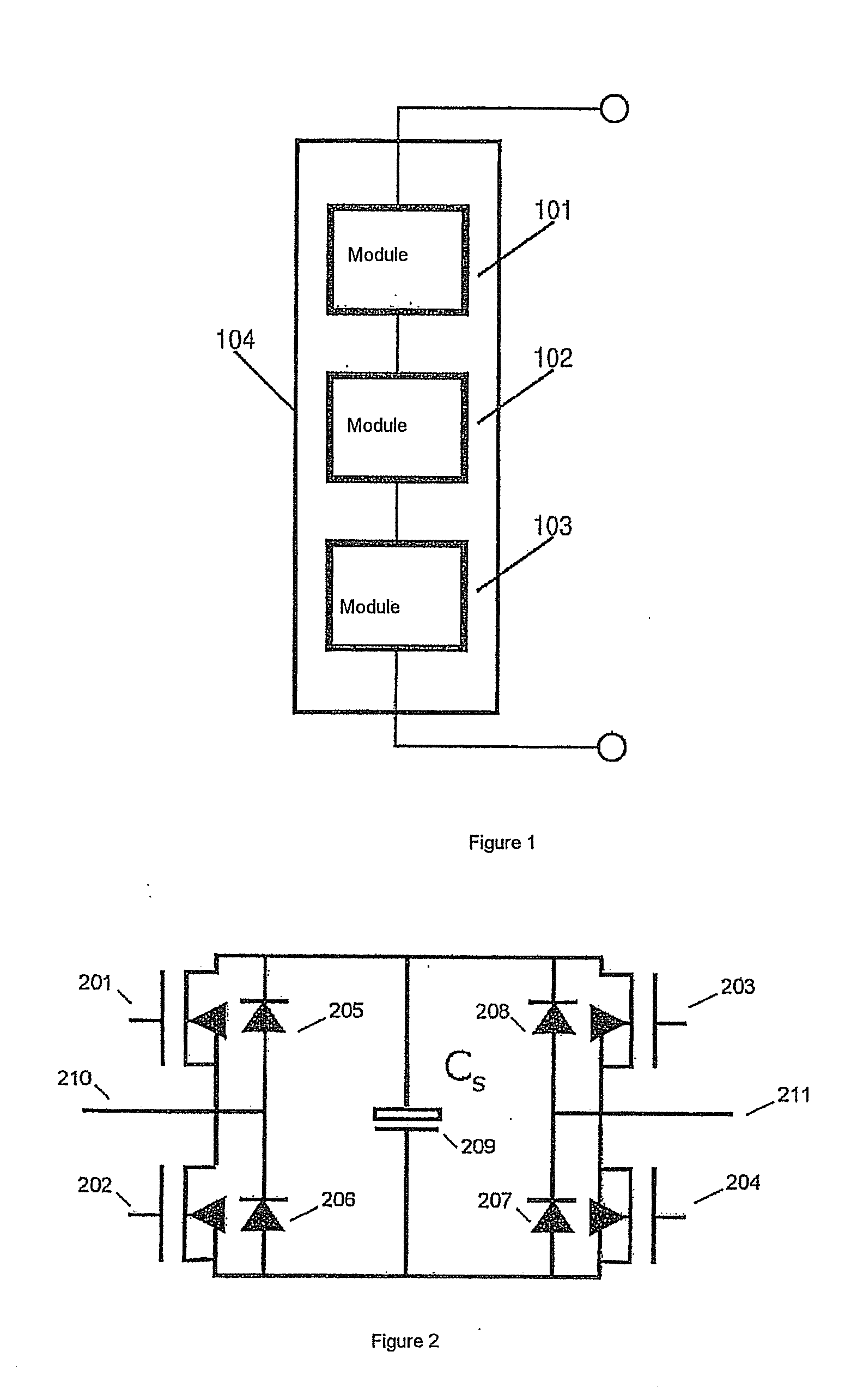
[0116]The invention is based on the recognition that a power converter that is to consist of a cascade connection of a plurality of identical individual modules should be designed such that the energy storage elements of said individual modules may be selectively connected either in parallel or in series. The interconnection of the individual modules may be fixed beforehand, so that it is only possible to specify whether the energy storage elements of the individual modules are to be connected in parallel or in series via the internal switching elements. At the same time, the topology of the internal switching elements should ensure that the voltage load of said switching elements is not substantially greater than the maximum voltage of the energy storage elements.

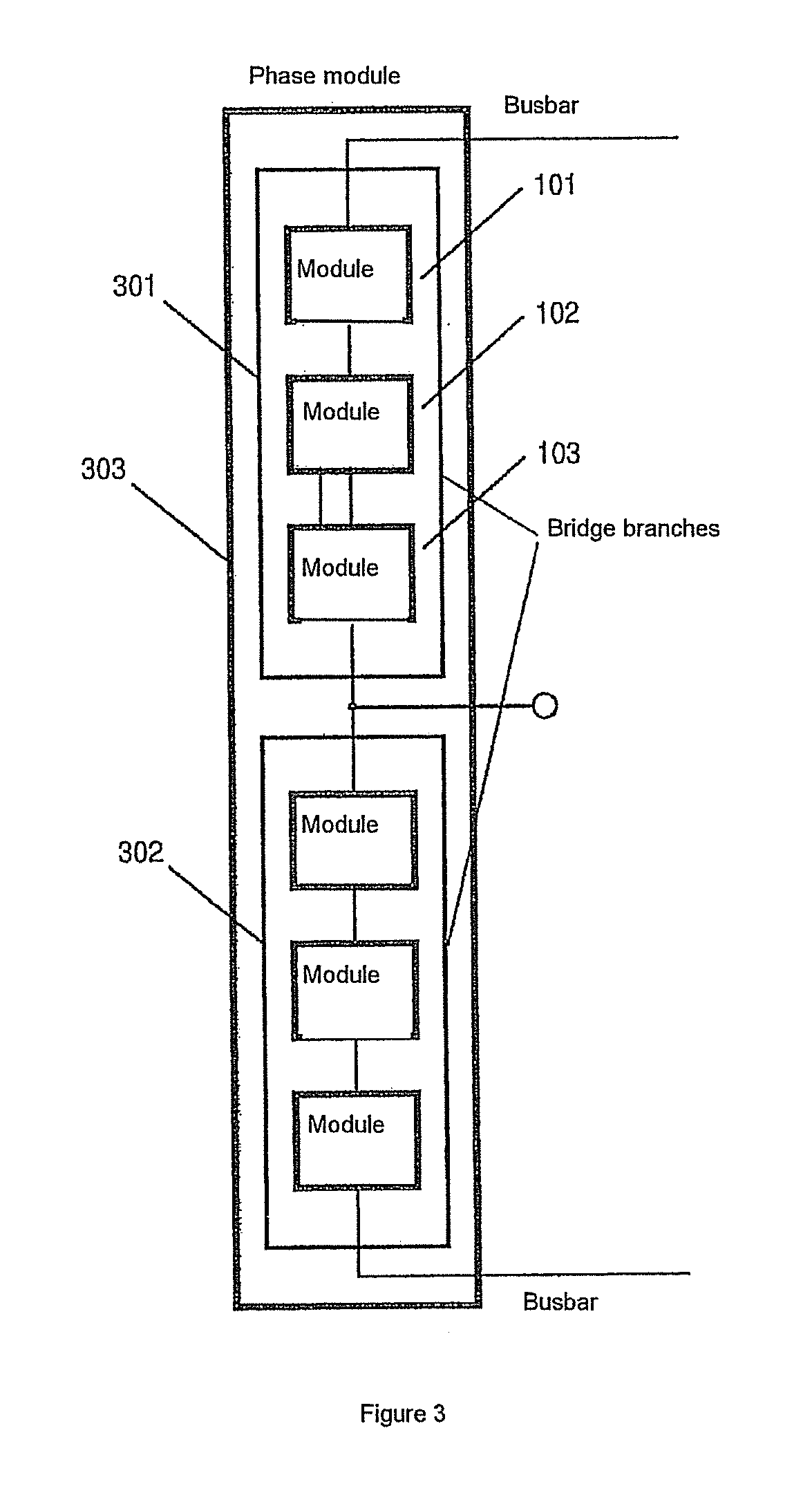
[0117]FIG. 7 shows an example of a possible external wiring arrangement of three individual modules 701, 702 and 703 according to the invention to form a cascade connection, such that, for example, a bridge branch of a pow...


PUM


Abstract

The present invention describes an electrical converter system for power supply systems, comprising at least two identical individual modules connected consecutively, characterised in that each individual module have at least four internal switching elements, at least one energy storage element and at least four connectors, wherein the connectors are paired and serve as a first and a second terminal pair; the internal switching elements of each individual module are designed in such manner that they are able to selectively connect one or both connectors of each terminal pair to the energy storage element; the cascaded connection of at least two individual modules is made in such manner that the connectors in the second terminal pair of a preceding individual module are each connected to the connectors of the first terminal pair in the respective following individual module, and at least one terminal of the first terminal pair of the first individual module of the cascaded connection and at least one terminal of the second terminal pair of the last individual module of the cascaded connection serve as terminals for the cascaded connection; and wherein the switching elements of the respective individual modules in the cascaded connection of at least two individual modules connect their respective energy storage element to the terminals of the cascaded connection in such manner that a selective serial or parallel connection of the energy storage elements is made.

Description

[0001]The invention relates to a special embodiment of a direct converter and the individual modular components thereof. The direct converter may be designed for single- or multiphase operation and on the input side may convert direct or alternating current to a direct or alternating current with any phasing or frequency. Converters of such kind have a wide variety of application possibilities; for example, they can be used to ensure controlled power supply to electric machines, and also for integrating direct current sources (battery accumulator units, solar systems) in an alternating current network.BACKGROUND OF THE INVENTION[0002]A large proportion of all energy consumed and generated is electrical energy. Electrical energy can be converted into a range of current-voltage combinations; on the other hand, in terms of chronological sequence, electrical energy can be converted from DC voltage to AC or three-phase voltage (with variable or fixed frequency) and vice versa. This conve...

Claims


Application Information

Patent Timeline
Patent Type & Authority Applications(United States)
IPC IPC(8): H02M1/42
CPCH02M1/42H02M7/483H02M7/4835H02M7/49
Inventor WEYH, THOMAS
Owner TECH UNIV MUNCHEN
Why Eureka
Try Eureka