
Liquid ejecting apparatus

a technology of liquid ejecting apparatus and ejector, which is applied in the direction of printing mechanism, power drive mechanism, printing, etc., can solve the problems of not being able to improve the widened ink channel and the inability to automatically perform replacement cleaning

Active Publication Date: 2014-02-20
SEIKO EPSON CORP
View PDF3 Cites 6 Cited by
  • Summary
  • Abstract
  • Description
  • Claims
  • Application Information

AI Technical Summary

Benefits of technology

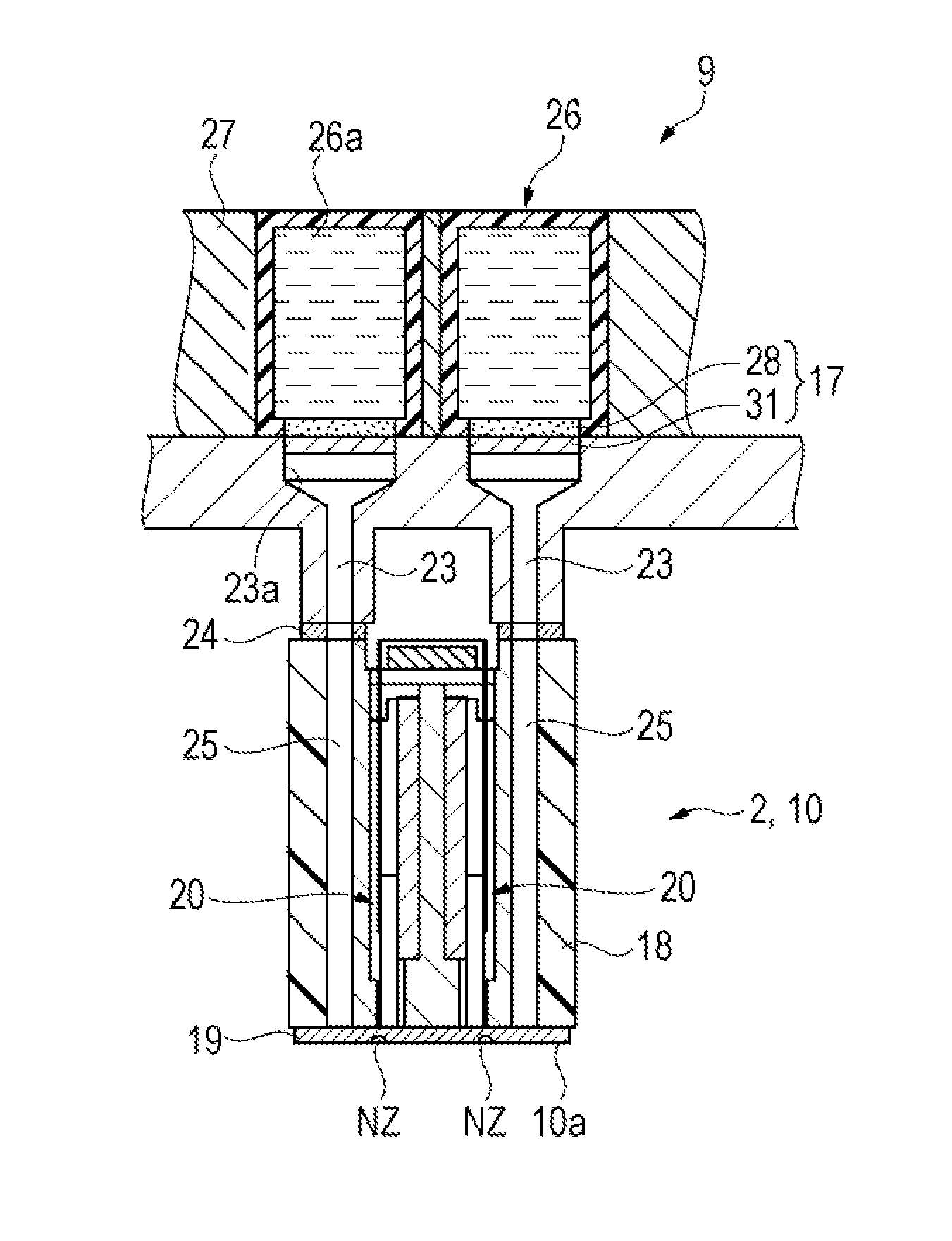
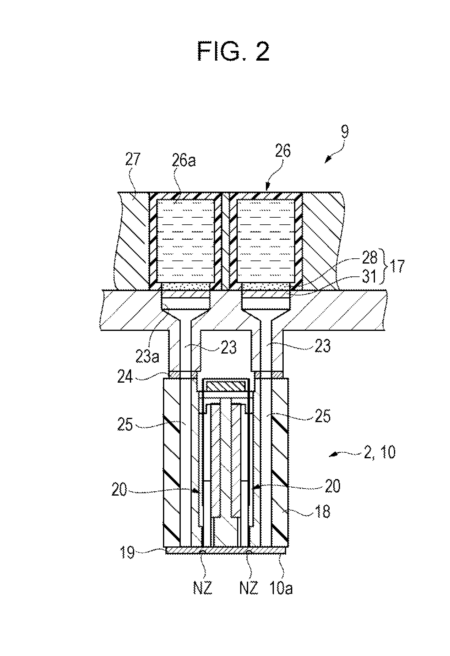
This patent is about a liquid ejecting apparatus that can achieve good ink ejection even if it uses a method for supplying ink from an external tank instead of cartridges. The ejecting head has a filter and a liquid absorption member that comes into contact with the liquid tank, so the channel within the ejecting head is not necessary. As a result, maintenance such as sucking bubbles from the channel can be performed less frequently, leading to better liquid ejection properties. The apparatus also has a detection unit to detect when the liquid tank is attached or removed, allowing for timely maintenance without performing unnecessary operations. Additionally, the apparatus prevents leakage of liquid from the tank even if the meniscus formed at the gas-liquid interface is broken.

Problems solved by technology

However, in the case of employing the aforementioned method in which a connector is mounted in the ink jet recording apparatus instead of cartridges and the ink is supplied to the ejecting head from an external tank, the connector is never replaced after being mounted; accordingly, there is a problem in that the replacement cleaning is not executed automatically, and thus ejection problems and the like caused by bubbles being produced at the widened ink channel are not ameliorated.

Method used


Image

  • Liquid ejecting apparatus
  • Liquid ejecting apparatus
  • Liquid ejecting apparatus

Examples


first embodiment

[0030]Hereinafter, embodiments of the invention will be described with reference to the drawings. Note that in the drawings, the scale of the various members is illustrated as being different from the actual scale in order to enable those members to be visible in the drawings. The following embodiments describe examples of a liquid ejecting apparatus embodied as an ink jet printer (called simply a “printer” hereinafter).

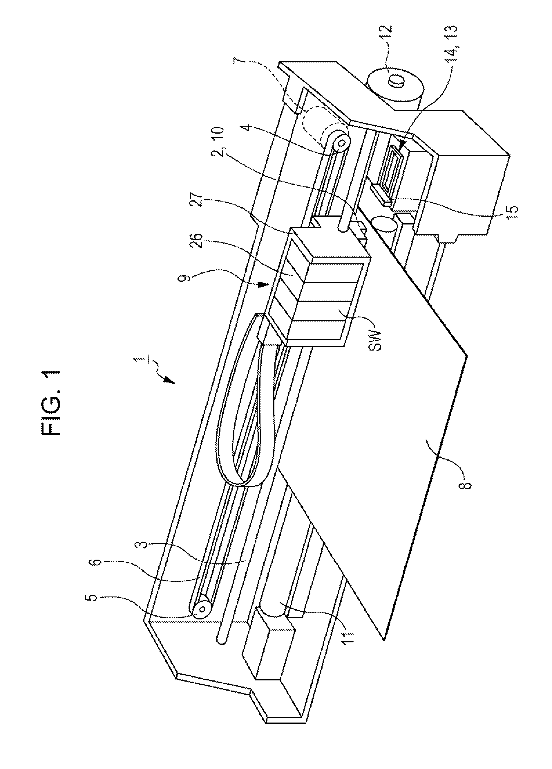
[0031]FIG. 1 is a diagram illustrating the overall configuration of a printer according to a first embodiment.

[0032]A printer (liquid ejecting apparatus) 1 includes a head unit (carriage) 2 that is attached in a mobile state to a guide shaft 3, as shown in FIG. 1.

[0033]The head unit (carriage) 2 is connected to a timing belt 6 that is stretched between a driving pulley 4 and a slave pulley 5. The driving pulley 4 is connected to a rotational shaft of a driving motor 7. Accordingly, the head unit (carriage) 2 moves in a width direction (a main scanning direction) of a...

second embodiment

[0081]A printer (liquid ejecting apparatus) 101 according to a second embodiment will now be described. The difference between this embodiment and the first embodiment lies in the peripheral structure of an ink supply mechanism IS that corresponds to the ink cartridges (liquid receptacles) 26 of the first embodiment; the rest of the configuration is the same. Accordingly, the following will describe only the peripheral structure of the ink supply mechanism IS, and descriptions of the rest of the configuration will be omitted or simplified. Note that configurations and members that are the same as in the first embodiment will be described as having the same reference numerals.

[0082]FIG. 7 is a diagram illustrating the overall configuration of a printer according to the second embodiment.

[0083]Instead of the ink cartridges (liquid receptacles) 26 of the first embodiment, the ink supply mechanism IS supplies ink to the recording head (ejecting head) 10 from ink tanks (external liquid r...


PUM


Abstract

A liquid ejecting apparatus includes a carriage having a removable liquid receptacle that holds a liquid or a removable connector connected via a flexible liquid channel to an external liquid receptacle that holds a liquid, an ejecting head, mounted in the carriage, that has a nozzle that ejects the liquid, and a maintenance unit that runs maintenance on the ejecting head; the ejecting head has a filter disposed so as to be capable of contact with a liquid absorption member provided in the liquid receptacle and in the connector.

Description

BACKGROUND[0001]1. Technical Field[0002]The present invention relates to liquid ejecting apparatuses.[0003]2. Related Art[0004]Ink jet recording apparatuses, in which an ejecting head and cartridges are disposed in a carriage that makes scans above a recording medium and a desired printing process is performed by ejecting ink (a liquid) supplied from the cartridges onto the recording medium from the ejecting head (recording head), are known as liquid ejecting apparatuses that have been used in the past. A connection method that employs ink supply pins is known as a technique for connecting the ejecting head and the cartridges in such an ink jet recording apparatus (for example, see JP-A-2002-200772).[0005]Incidentally, rather than mounting cartridges on the carriage, it is also conceivable to employ a method in which a connector is mounted on the carriage and connected to an external tank disposed outside of the recording apparatus via a flexible supply channel, and ink is supplied ...

Claims


Application Information

Patent Timeline
IPC IPC(8): B41J2/165
CPCB41J2/16517B41J2/16579B41J2/17546B41J25/34B41J2002/16573
Inventor TANAKA, TAKESHIKIMURA, HITOTOSHI
Owner SEIKO EPSON CORP
Learn More