Portable digital video camera configured for remote image acquisition control and viewing

a digital video camera and remote image acquisition technology, applied in the field of point-of-view (pov) video cameras or camcorders, can solve problems such as difficult use, and achieve the effect of convenient editing

Active Publication Date: 2014-02-20
CONTOUR IP HLDG
View PDF9 Cites 116 Cited by
  • Summary
  • Abstract
  • Description
  • Claims
  • Application Information

AI Technical Summary

Benefits of technology

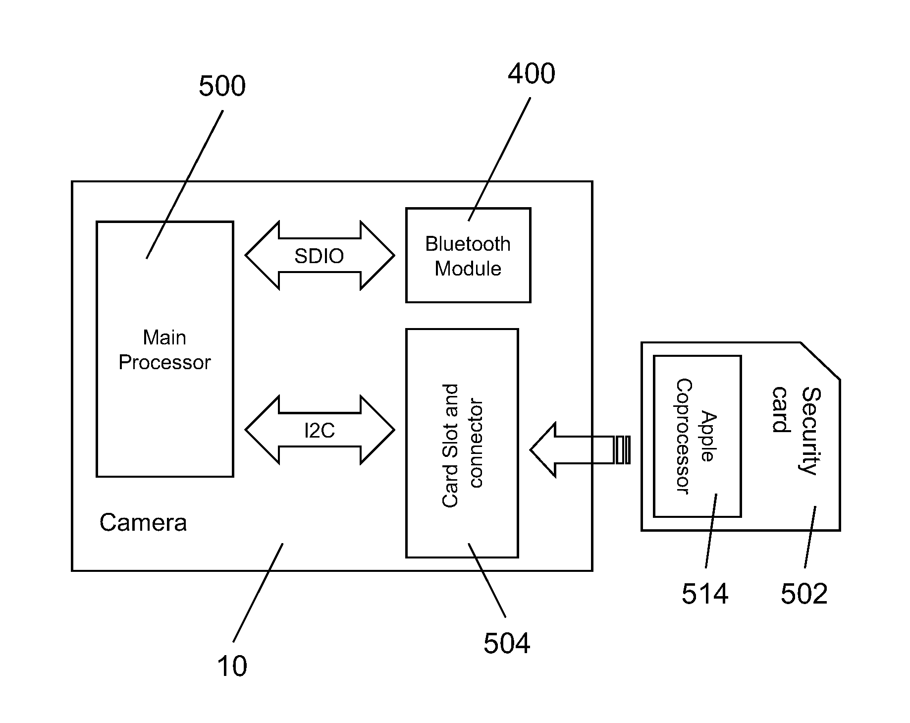
[0005]Preferred embodiments of a portable digital video camera or camcorder (hereinafter collectively, “video camera”) are equipped with global positioning system (GPS) technology for data acquisition and wireless connection protocol to provide remote image acquisition control and viewing. A wireless connection protocol, such as the Bluetooth® packet-based open wireless technology standard protocol, is used to provide control signals or stream data to a wearable video camera and to access image content stored on or streaming from a wearable video camera. Performing intelligent frame analysis of the image content enables picture setup optimization on one or more cameras simultaneously to enable multi-angle and three-dimensional video. A GPS receiver integrated in the video camera enables tracking of the location of the video camera as it acquires image information. The GPS receiver enables periodic capture of location once every few seconds with near pinpoint accuracy to bring together video and mapping. The inclusion of GPS technology introduces a new level of context to any video, making location, speed, time, and outside world conditions as important as the scene recorded. GPS capability makes it relatively easy to capture video within the action and share it online in seconds. For example, a user can watch an epic run down any mountain while tracking progress, speed, and elevation on a map. The GPS data, together with high definition video images, can be readily edited to organize video content, configure the video camera, and post stories online.
[0006]GPS ground plane customization and electrical coupling to the housing or other metal components of the video camera improves reception and performance. The ground plane is maximized by coupling it with an aluminum case that houses the video camera. The result is higher antenna gain and consequent enhanced signal reception when the video camera is mounted in multiple positions.
[0008]Simplified mounting of the wearable video camera is accomplished by rotating the horizon 180° so that the video camera can be mounted fully upside down as the picture remains in the proper orientation. Rotation of the horizon may be accomplished electrically or mechanically. A rotating mount with a locking feature that allows adjustment of the angle of the video camera when it is attached to a mounting surface uses an adhesive, a strap, or another connection option. The video camera housing is equipped with a scissor spring to assist in moving a slide switch actuator over a long travel range. A user wearing the video camera uses the slide switch actuator to initiate video image recording.

Problems solved by technology

These products are still in their infancy and may be difficult to use well.

Method used


Image

  • Portable digital video camera configured for remote image acquisition control and viewing
  • Portable digital video camera configured for remote image acquisition control and viewing
  • Portable digital video camera configured for remote image acquisition control and viewing

Examples


Embodiment Construction

[0064]FIGS. 3A, 3B, 3C, 3D, 3E, and 3F are, respectively, front perspective, back perspective, side elevation, front elevation, back elevation, and top plan views of an embodiment of an integrated hands-free, POV action sports digital video camera 10, and FIGS. 4A and 4B are front and back perspective views of, respectively, an alternative configuration and an alternative embodiment of digital video camera 10. For purposes of this description, the term “camera” is intended to cover camcorder(s) as well as camera(s). An example of such a digital video camera 10 is included in the Contour 1080P™ system, marketed by Contour, Inc., of Seattle, Wash.

[0065]FIGS. 5, 6, 7, 8A, and 8B show optical and mechanical components of digital video camera 10. With reference to FIGS. 3A-3F, 4A, 4B, 5, 6, 7, 8A, and 8B, some embodiments of digital video camera 10 include a manual horizon adjustment control system 12 including a manual horizon adjustment control for adjusting an orientation of a horizon...


PUM


Abstract

A wearable digital video camera (10) is equipped with wireless connection protocol and global navigation and location positioning system technology to provide remote image acquisition control and viewing. The Bluetooth® packet-based open wireless technology standard protocol (400) is preferred for use in providing control signals or streaming data to the digital video camera and for accessing image content stored on or streaming from the digital video camera. The GPS technology (402) is preferred for use in tracking of the location of the digital video camera as it records image information. A rotating mount (300) with a locking member (330) on the camera housing (22) allows adjustment of the pointing angle of the wearable digital video camera when it is attached to a mounting surface.

Description

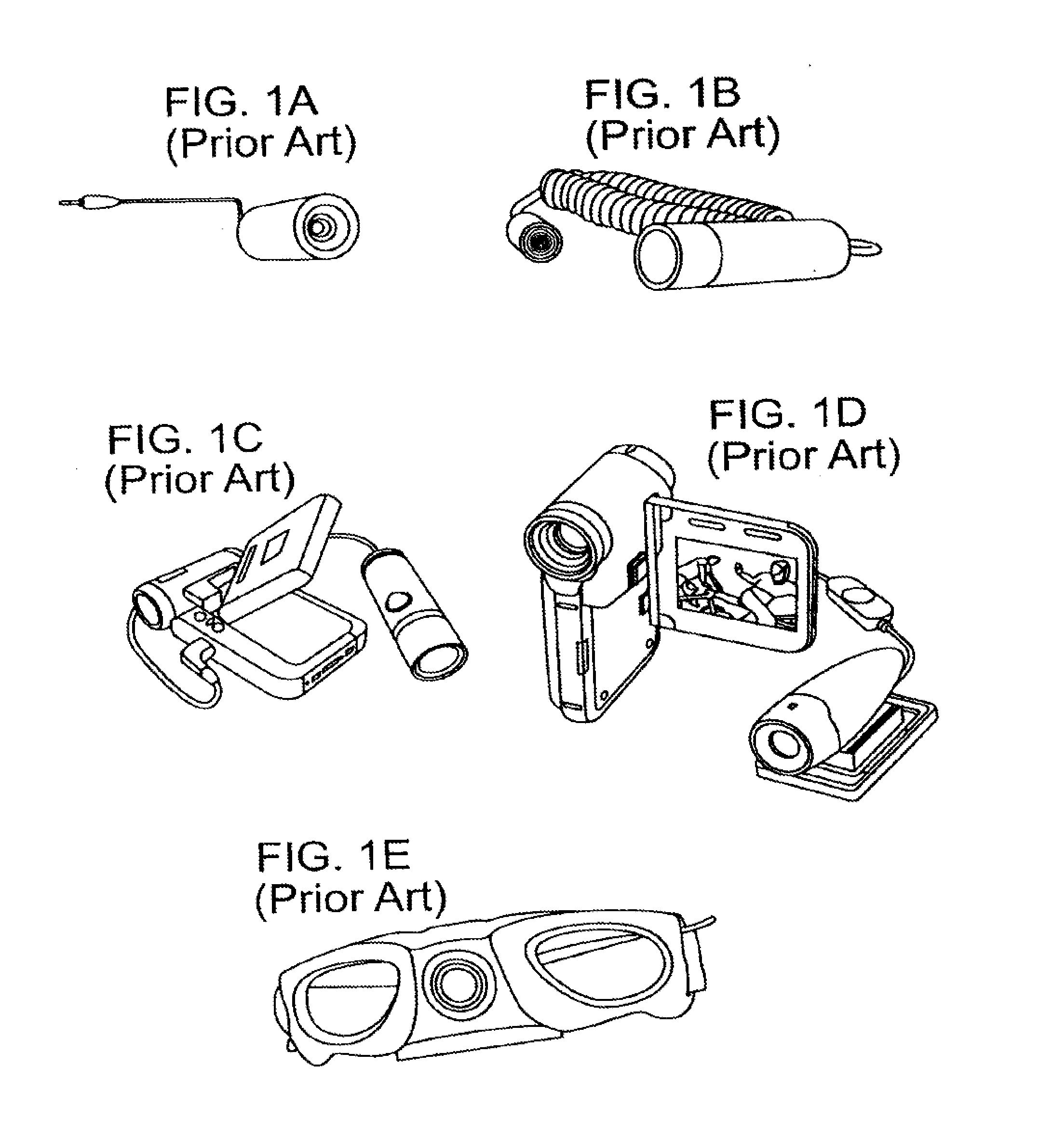
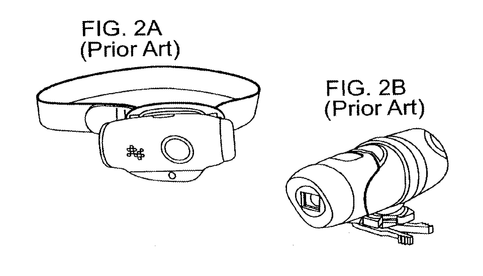
TECHNICAL FIELD[0001]This disclosure relates to point-of-view (POV) video cameras or camcorders and, in particular, to an integrated hands-free, POV action sports video camera or camcorder that is configured for remote image acquisition control and viewing.BACKGROUND INFORMATION[0002]First-person video cameras are a relatively new product category that have been adapted to capture POV video by action sports enthusiasts in a hands-free manner. Conventional first-person video cameras primarily comprise a lens that must be tethered to a separate digital video recorder or camcorder. FIGS. 1A and 1B present pictorial views of prior art first-person video cameras requiring a tethered lens approach to capturing first-person video recording. FIG. 1A presents a Twenty20™ device, and FIG. 1B presents a Viosport™ device. FIGS. 1C and 1D present pictorial views of prior art video cameras tethered to camcorders for implementing the tethered lens approach to capturing first-person video recording...

Claims


Application Information

Patent Timeline
Patent Type & Authority Applications(United States)
IPC IPC(8): H04N7/18
CPCH04N7/18G08C17/02H04N7/185G08C2201/93H04N5/76H04N23/51H04N23/66H04N23/661H04N23/55H04N23/50H04N23/617G08B13/19641G08B13/1966G08B13/19682G08B13/19684H04N7/181H04N7/183H04N21/21805H04N21/234363H04N21/2365H04N21/2385H04N21/25825H04N21/2662H04N21/4621G01S19/19H04N5/28H04W80/02G01S19/42G16H40/67
Inventor O'DONNELL, LAURAMANDER, RICHARDDENTON, MICHAELBODLEY, BENTOMPKINS, ALANGURGANUS, KEITHBARNSDALE, KELVIN P.THIRD, SIMONPIERCE, CARMPERKINS, CARL
Owner CONTOUR IP HLDG
Why Eureka
Try Eureka