Ganged single axis solar tracker and its drive system

a solar tracker and drive system technology, applied in solar heat systems, solar thermal energy generation, lighting and heating apparatus, etc., can solve the problems of limiting the total area of solar tracker arrays driven by each motor/driver, high cost of solar tracker array using this technology, and high cos

Inactive Publication Date: 2014-02-27
SUZHOU JINSHAN SOLAR SCI & TECH
View PDF56 Cites 18 Cited by
  • Summary
  • Abstract
  • Description
  • Claims
  • Application Information

AI Technical Summary

Benefits of technology

[0017]The ganged single axis tracker and its drive mechanism has the following advantages: firstly, solar trackers can be conveniently placed in a mirror layout about the rotary drive axis, and the maximum force endured by the linkage member equals only to the forces from half of the entire solar array. In another words, the linkage member with the same size in the present invention can drive twice as many solar panels as per the prior art. Secon

Problems solved by technology

The biggest challenge the solar energy is currently facing is its relatively high cost.
The prior art single axis trackers typically have one motor/drive per tracker row, thus limiting the total area of solar receivers driven by each motor/drive.
Solar tracker array using this technology will have high costs due to generally increased material usage, field construction work, as well as maintenance requirements.
The system has also limitat

Method used


Image

  • Ganged single axis solar tracker and its drive system
  • Ganged single axis solar tracker and its drive system
  • Ganged single axis solar tracker and its drive system

Examples


third embodiment

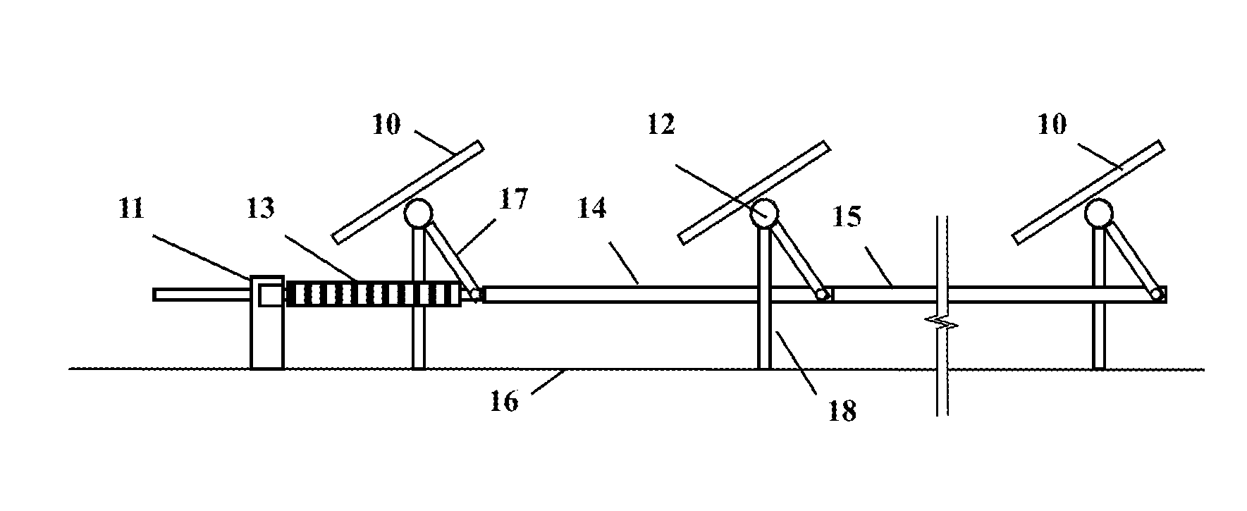
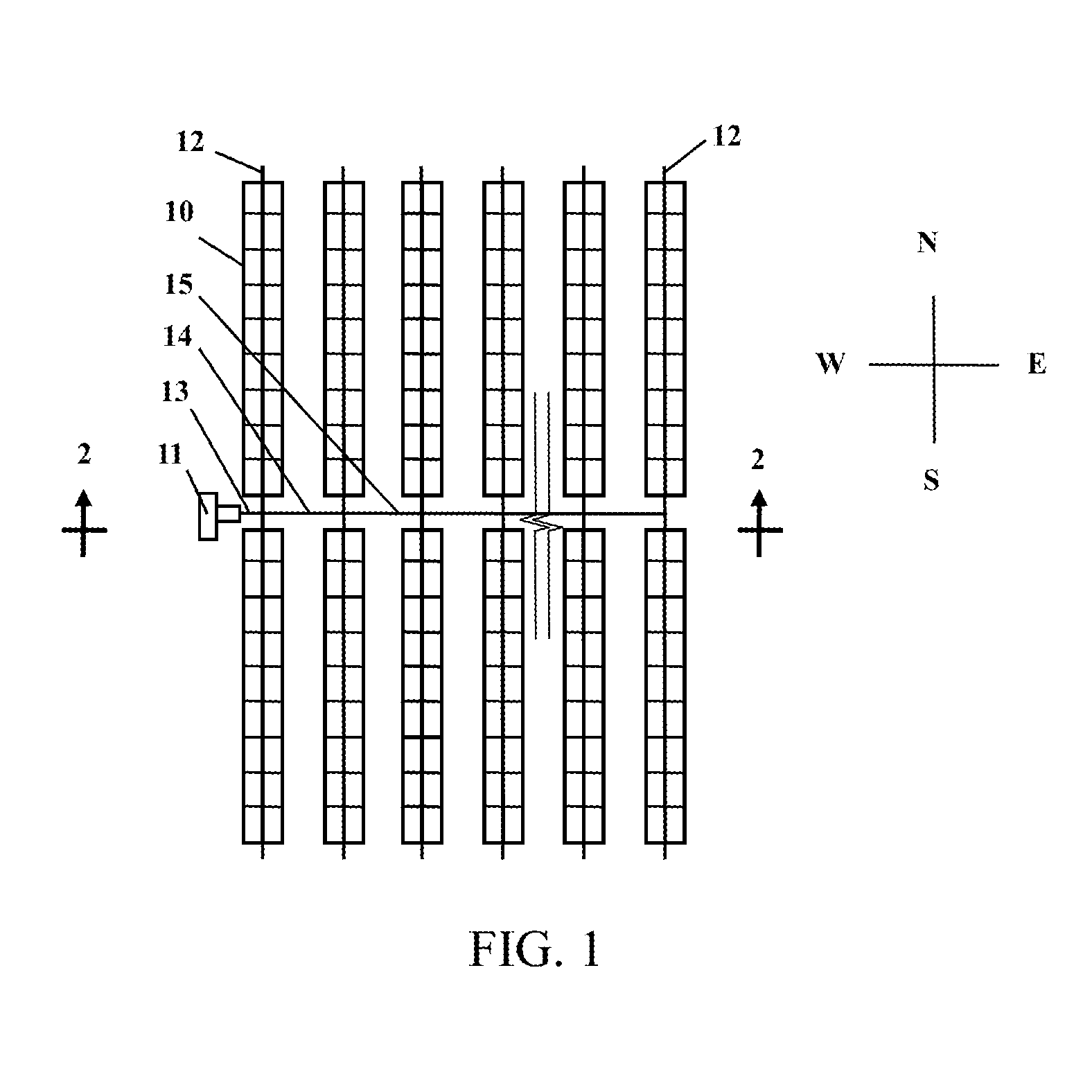
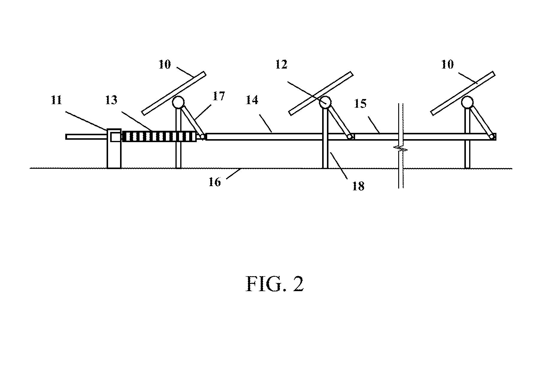
[0035]this invention is shown in FIG. 7. In this example, the drive axis is located near the center of the tracker array while it is apart from any tracker rotation axis.

fourth embodiment

[0036]In this invention as shown in FIG. 8, the drive axis is located on one side of and apart from the tracker array.

[0037]In any particular applications of the present invention, solar receivers can all have the same or various initial tracker angles; the tracker rotation beam can be of round or square cross section, a truss or any other composite structure.

[0038]In all embodiments as shown the tracker axes are flat. It is not difficult to persons skilled in the art that the tracker axes can be aligned tilted to the ground or vertical.

[0039]The term “ground” as used in reference to the foundation is not limited to earth or soils, but can be a rooftop or any other supporting structures.


PUM


Abstract

The present invention involves a ganged single axis solar tracker and its drive system having at least two rows of solar trackers and a drive mechanism. Each tracker row shares one common rotation axis and the at least two tracker rows are placed in parallel. At least one torque arm is rigidly and perpendicularly connected to the each tracker rotation axis. The drive mechanism has at least one rotary actuator, such as a slew drive, whose rotation axis is parallel to the tracker rotation axes. At least one drive torque arm is rigidly and perpendicularly connected to the drive rotation axis. The drive torque arm and the tracker torque arms are hinge connected with a series of rigid beams. The linkage beams are perpendicular to the tracker and drive rotation axes. The rotary drive rotates and creates a rotation movement. The drive torque arm follows the rotation movement of the drive, which consequently converts a linear push-pull movement in the linkage beams. The linkage beams push and pull the tracker torque arms, rocking the at least two rows of solar trackers to rotate about their axes and to follow the sun's movement.

Description

BACKGROUND OF THE INVENTION[0001]1. Field of the Invention[0002]This invention relates to solar energy production and more particularly to an apparatus for driving a number of rows of solar receivers to follow the motion of the sun relative to the earth.[0003]2. Description of the Related Art[0004]Solar energy has gradually become an important alternative power resource to help achieve the goal of sustainable development. Solar power has a few unique advantages such as it is clean, abundant, and it produces when the consumption is high. The biggest challenge the solar energy is currently facing is its relatively high cost. Solar tracking systems can improve incident angles of solar receivers such as solar thermal or photovoltaic modules (PV). These tracking devices have been successfully used to improve power production efficiency, and thus to reduce solar power generation costs.[0005]The prior art single axis trackers typically have one motor / drive per tracker row, thus limiting th...

Claims


Application Information

Patent Timeline
IPC IPC(8): F24J2/54
CPCF24J2/541F24S20/20F24S30/425F24S2030/131F24S2030/136F24S30/42F24S50/20F24S2030/134Y02E10/47
Inventor ZHOU, YIN
Owner SUZHOU JINSHAN SOLAR SCI & TECH
Why Eureka
Try Eureka