Sensor arrangement and method

a technology of sensors and sensors, applied in the field of sensor arrangement, can solve the problems of a small sensor signal being overloaded, the procedure is not optimal in particular with high amplification, and the use signal cannot be extended to the subsequent processing chain, so as to reduce the offset

Active Publication Date: 2014-02-27
FRAUNHOFER GESELLSCHAFT ZUR FOERDERUNG DER ANGEWANDTEN FORSCHUNG EV
View PDF2 Cites 5 Cited by
  • Summary
  • Abstract
  • Description
  • Claims
  • Application Information

AI Technical Summary

Benefits of technology

[0022]It is one advantage of these embodiments that the supply current for the sensor element itself serves as a reference for setting the feed current, which m

Problems solved by technology

If the offset signal is too large, however, the amplifier is driven into confinement by this offset signal and the useful signal can no longer reach the subsequent processing chain.
The compensation is independent of the internal resistance of the sensor but the problem of the possible overload with a small sensor signal remains.
Current circuits do have a higher dynamic range that voltage circuits, but this procedure is not optimal in particular wit

Method used


Image

  • Sensor arrangement and method
  • Sensor arrangement and method
  • Sensor arrangement and method

Examples


Embodiment Construction

[0032]Before embodiments of the present invention are described in the following with reference to the accompanying drawings, it is to be noted that like elements or elements of the same function are provided with the same reference numerals and that a repeated description of those elements is omitted. Descriptions of elements having the same reference numerals are thus mutually interchangeable.

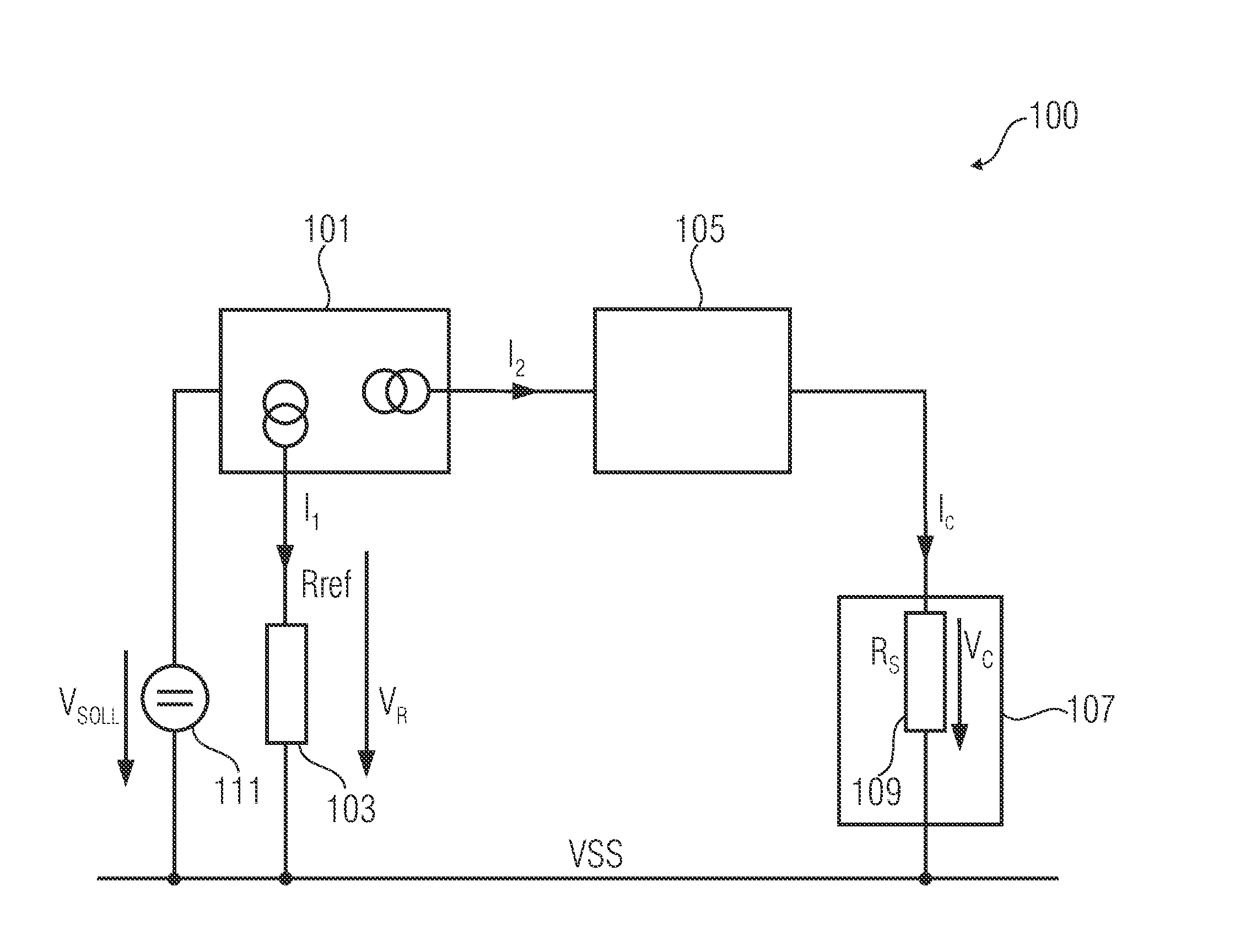
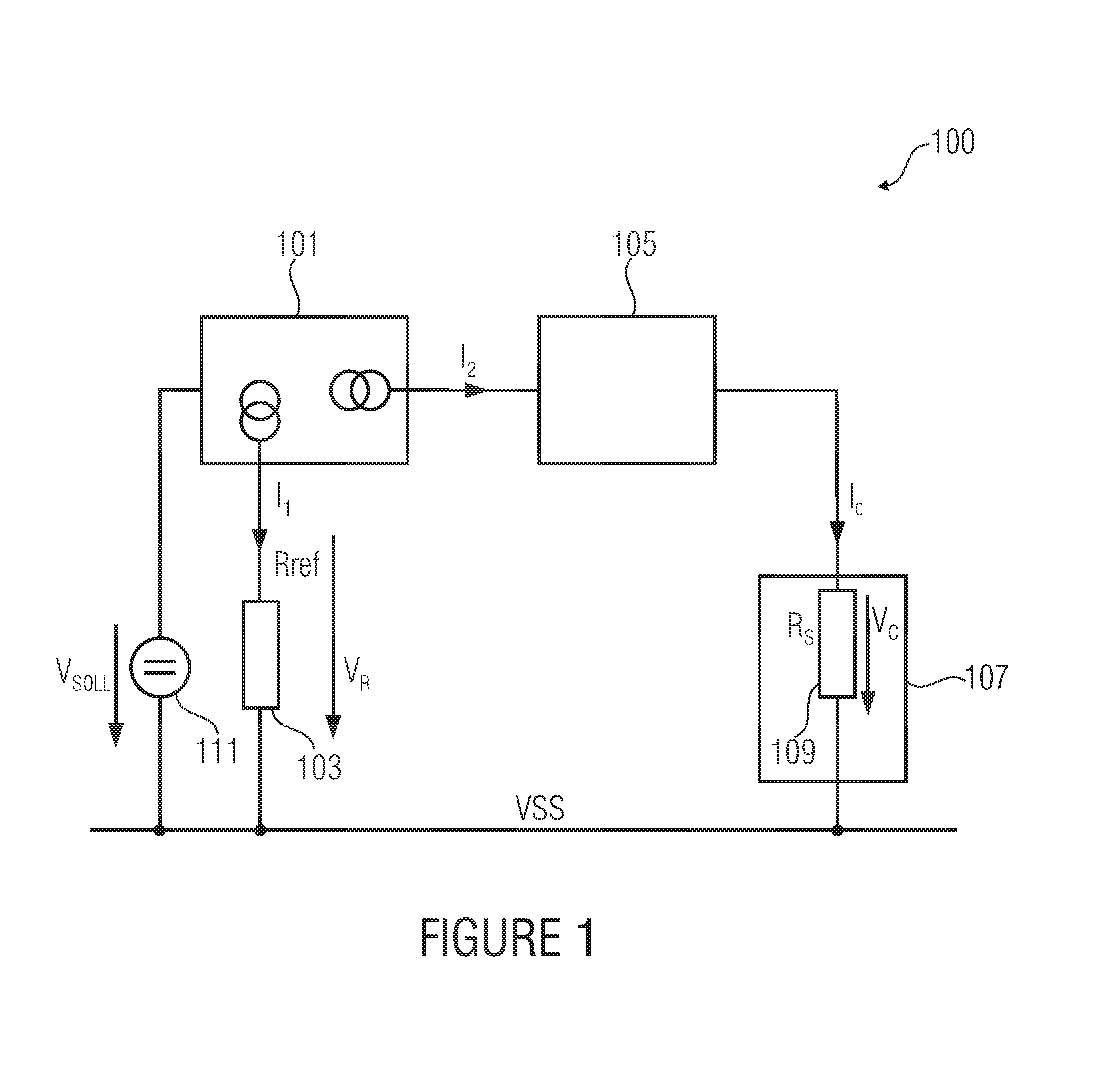
[0033]FIG. 1 shows a block diagram of a sensor arrangement 100 according to one embodiment of the present invention.

[0034]The sensor arrangement 100 comprises a current regulator 101, a reference resistance 103 (also referred to as Rref), a feed current scaling means 105 and a sensor element 107 having an internal resistance 109 (also referred to as Rs).

[0035]The internal resistance 109 of the sensor element 107 and the reference resistance 103 comprise a given ratio with respect to each other.

[0036]The current regulator 101 is implemented to provide a reference current by the reference resis...


PUM


Abstract

A sensor arrangement has a current regulator, a reference resistance a feed current scaler and a sensor element having an internal resistance, the internal resistance of the sensor element and the reference resistance having a predetermined ratio. The current regulator is implemented to provide a reference current by the reference resistance and to change the reference current in response to an interference influence-conditioned change of the reference resistance such that the voltage decreasing across the reference resistance remains in a predetermined range around an applied set voltage. The current regulator is implemented to provide a feed current to the feed current scaler and to change a magnitude of the feed current depending on a magnitude of the reference current. The feed current scaler is implemented to feed a scaled feed current into the sensor element to scale a voltage according to the scaling of the feed current.

Description

CROSS-REFERENCE TO RELATED APPLICATIONS[0001]This application is a continuation of copending International Application No. PCT / EP2012 / 056947, filed Apr. 16, 2012, which is incorporated herein by reference in its entirety, and additionally claims priority from German Application No. DE 102011017640.3-52, filed Apr. 27, 2011, which is also incorporated herein by reference in its entirety.BACKGROUND OF THE INVENTION[0002]Embodiments of the present invention provide a sensor arrangement as it may, for example, be used in combination with Hall sensors. Further embodiments provide a method which may, for example, be used in combination with Hall sensors.[0003]Basically, the offset of a sensor and that of a subsequent amplifier are determined or compensated separately from the useful signal, as otherwise an unknown value of the measurement is overlaid which is at best constant but mostly depends on the temperature. In the measurement of very small signals, the offset signal may well be a m...

Claims


Application Information

Patent Timeline
IPC IPC(8): G01R35/00
CPCG01R35/005G01D3/028
Inventor HERZER, ELMARSCHLAG, ULRICHSAUERER, JOSEF
Owner FRAUNHOFER GESELLSCHAFT ZUR FOERDERUNG DER ANGEWANDTEN FORSCHUNG EV
Why Eureka
Try Eureka