
Electromagnet device and electromagnetic relay using the same

a technology of electromagnetic relay and electromagnetic device, which is applied in the direction of magnets, relays, magnetic bodies, etc., can solve the problems of reducing magnetism and weakening the retention force between the movable iron piece and the iron core, and achieves strong retention force

Active Publication Date: 2014-02-27
ORMON CORP
View PDF32 Cites 0 Cited by
  • Summary
  • Abstract
  • Description
  • Claims
  • Application Information

AI Technical Summary

Benefits of technology

The present invention provides an electromagnetic device that overcomes the limitations of conventional art by maintaining a strong retention force between a movable iron piece and an iron core, which is useful for an electromagnetic relay.

Problems solved by technology

However, since the attracted portion and the attracting surface are flat and smooth in the electromagnet device, this lead to various problems such as magnetic flux flowing between the movable iron piece and the iron core spreads which reduces magnetism and thereby weaken a retention force between the movable iron piece and the iron core.

Method used


Image

  • Electromagnet device and electromagnetic relay using the same
  • Electromagnet device and electromagnetic relay using the same
  • Electromagnet device and electromagnetic relay using the same

Examples


Embodiment Construction

[0031]The present invention is described hereinafter by various embodiments with reference to the accompanying drawings, wherein reference numerals used in the accompanying drawings correspond to the like elements throughout the description. Further, while discussing various embodiments, cross reference will made between the figures. In order to achieve full description and explanation, specific details have been mentioned to provide thorough and comprehensive understanding of various embodiments of the present invention. However, said embodiments may be utilized without such specific details and in various other ways broadly covered herein.

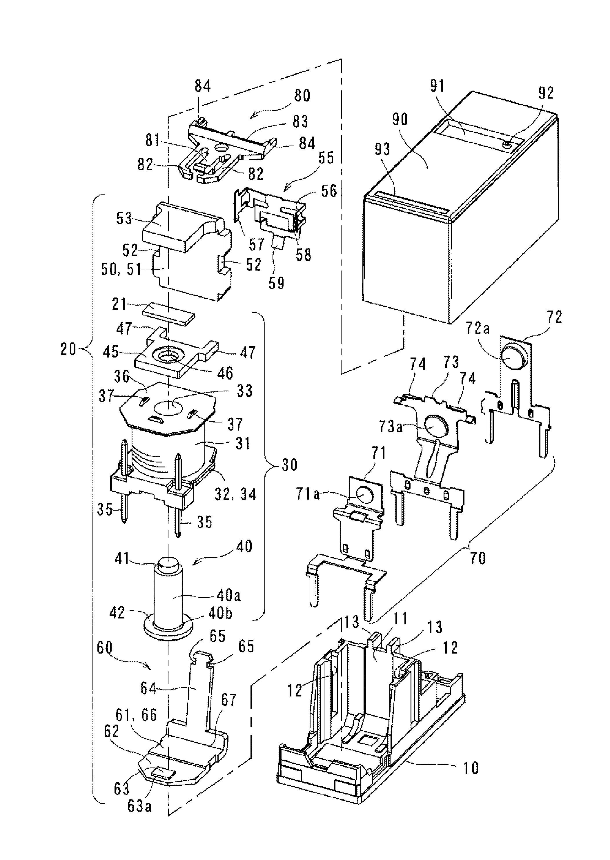
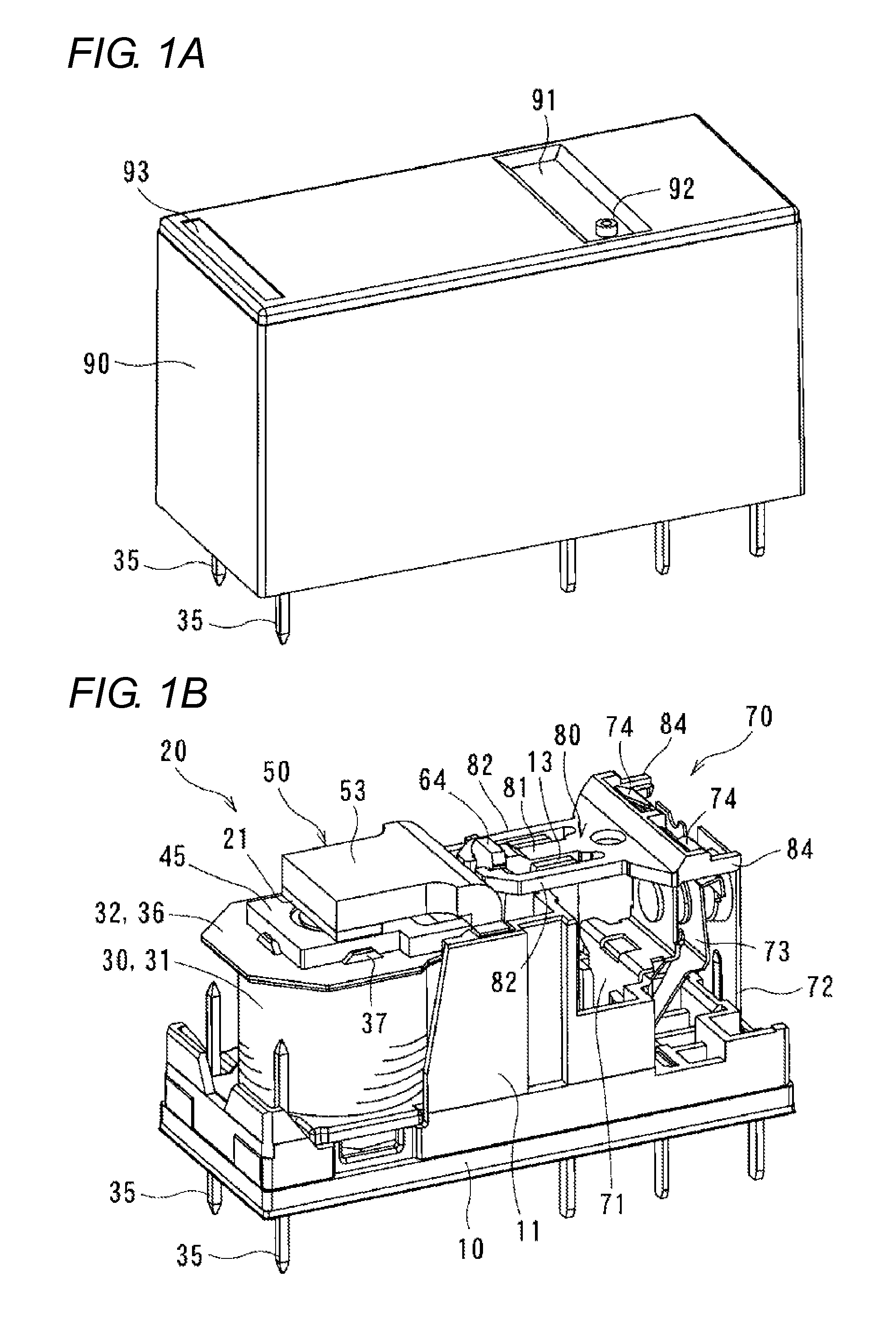
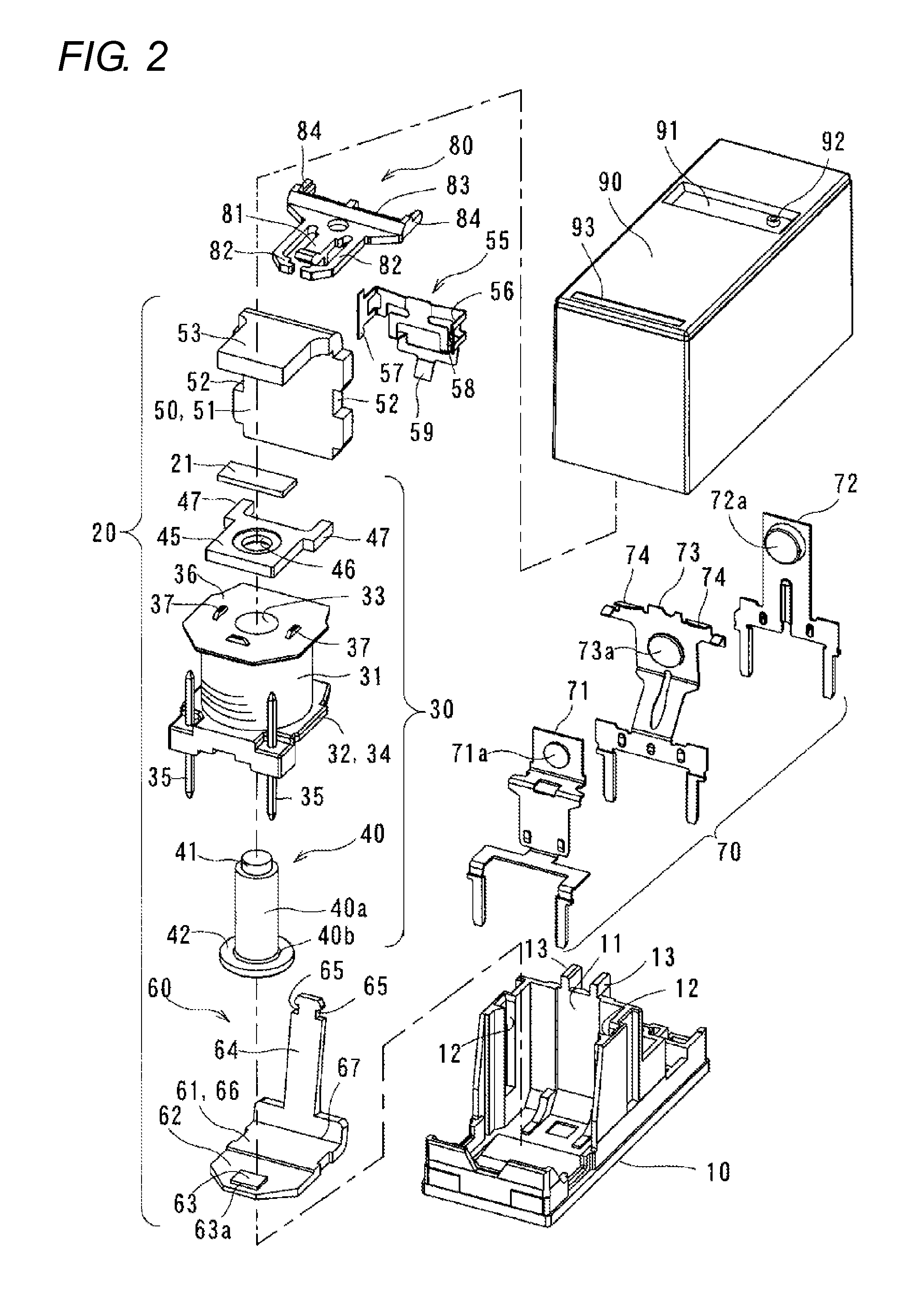
[0032]An electromagnet device according to one of the embodiment of the present invention is described with reference to FIGS. 1A to 12B. The electromagnet device is incorporated into a latching type electromagnetic relay as illustrated in FIGS. 1A to 8B. In this case, the electromagnet device includes a base 10, an electromagnet device 20, a con...


PUM


Abstract

The present invention provides an electromagnet device including: an electromagnet block having a spool around which a coil is wound and an iron core inserted in a central hole of the spool; a yoke connected to an end portion of the iron core via a permanent magnet; a movable iron piece pivotably supported on a pivoting shaft center located at an end face edge portion of the yoke, the movable iron piece is adapted to pivot on a basis of magnetization and demagnetization of the electromagnet block, and a protrusion having a linear edge portion which extends in parallel to the pivoting shaft center and the protrusion protrudes from at least either the movable iron piece or the iron core, the protrusion protrudes in a facing direction in which the movable iron piece and the iron core face each other.

Description

CROSS REFERENCE TO RELATED APPLICATION[0001]This application claims benefit of priority to Japanese Patent Application No. 2012-185882, filed on Aug. 24, 2012 of which the full contents are herein incorporated by reference.BACKGROUND OF THE INVENTION[0002]The present invention relates to an electromagnet device.[0003]Japanese Patent Publication No. 2004-164948 (Also published as U.S. Pat. No. 7,205,870) discloses one of the conventional electromagnetic device to be used in an electromagnetic relay. The electromagnet device disclosed in said document includes an attracted portion of a movable iron piece and an attracting surface of an iron core wherein both the movable iron piece and the attracting surface are flat and smooth to achieve attraction.[0004]However, since the attracted portion and the attracting surface are flat and smooth in the electromagnet device, this lead to various problems such as magnetic flux flowing between the movable iron piece and the iron core spreads whic...

Claims


Application Information

Patent Timeline
Patent Type & Authority Applications(United States)
IPC IPC(8): H01H50/20
CPCH01H50/20H01H50/26H01H50/36H01H50/42H01H50/642H01H51/2236
Inventor SUMINO, TOSHIFUMIYAMAMOTO, MASAAKISAKAI, ICHINORIKATO, TATSUROMURAKAMI, KAZUYA
Owner ORMON CORP
Learn More