
Clamping device and workpiece conveying robot
a technology of workpiece and conveying robot, which is applied in the direction of manipulators, gripping heads, load-engaging elements, etc., can solve the problems of workpiece space apprehension, and achieve the effect of high positional precision, high positional precision and high positional precision
- Summary
- Abstract
- Description
- Claims
- Application Information
AI Technical Summary
Benefits of technology
Problems solved by technology
Method used
Image

Examples
Embodiment Construction
[0040]Hereinafter, an embodiment of the present invention will be described with reference to the drawings.
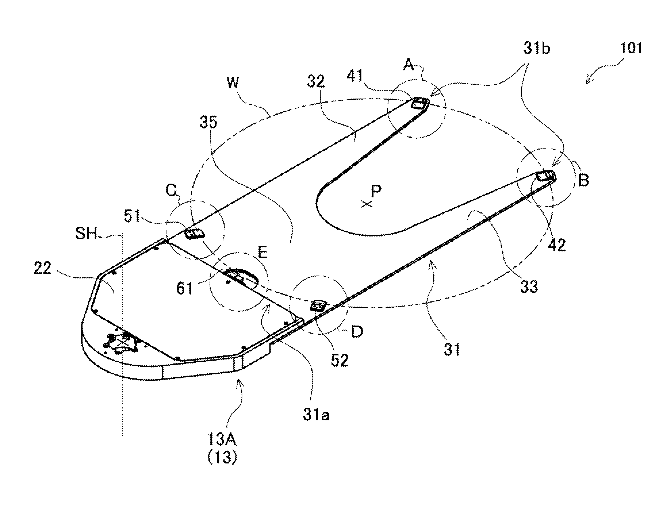
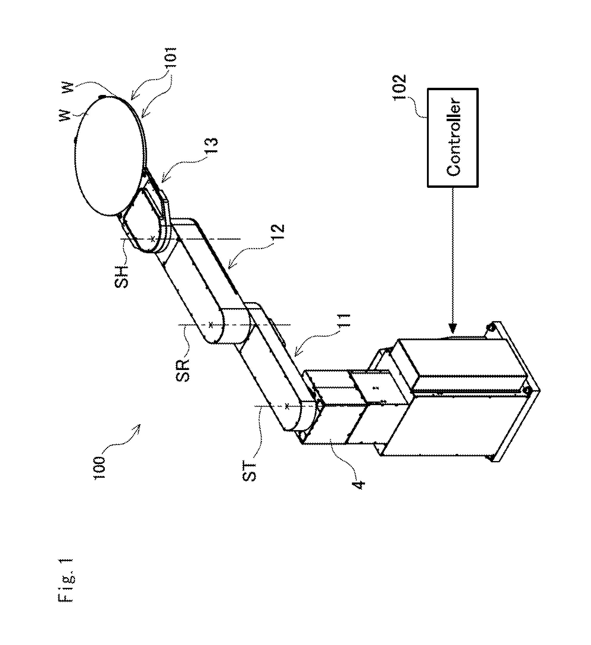
[0041]FIG. 1 shows a workpiece conveying robot 100 in the embodiment. This workpiece conveying robot 100 is capable of receiving a workpiece W formed in the shape of a disk such as a semiconductor wafer and then conveying and delivering the received workpiece to a device in a next step. In the drawings employed for illustration in the embodiment, same reference numerals are assigned to same constituent elements of the conventional clamp device illustrated using FIG. 11 and FIG. 12. In addition, in the following description, a side face of a workpiece W designates an outer circumferential face of a disk.
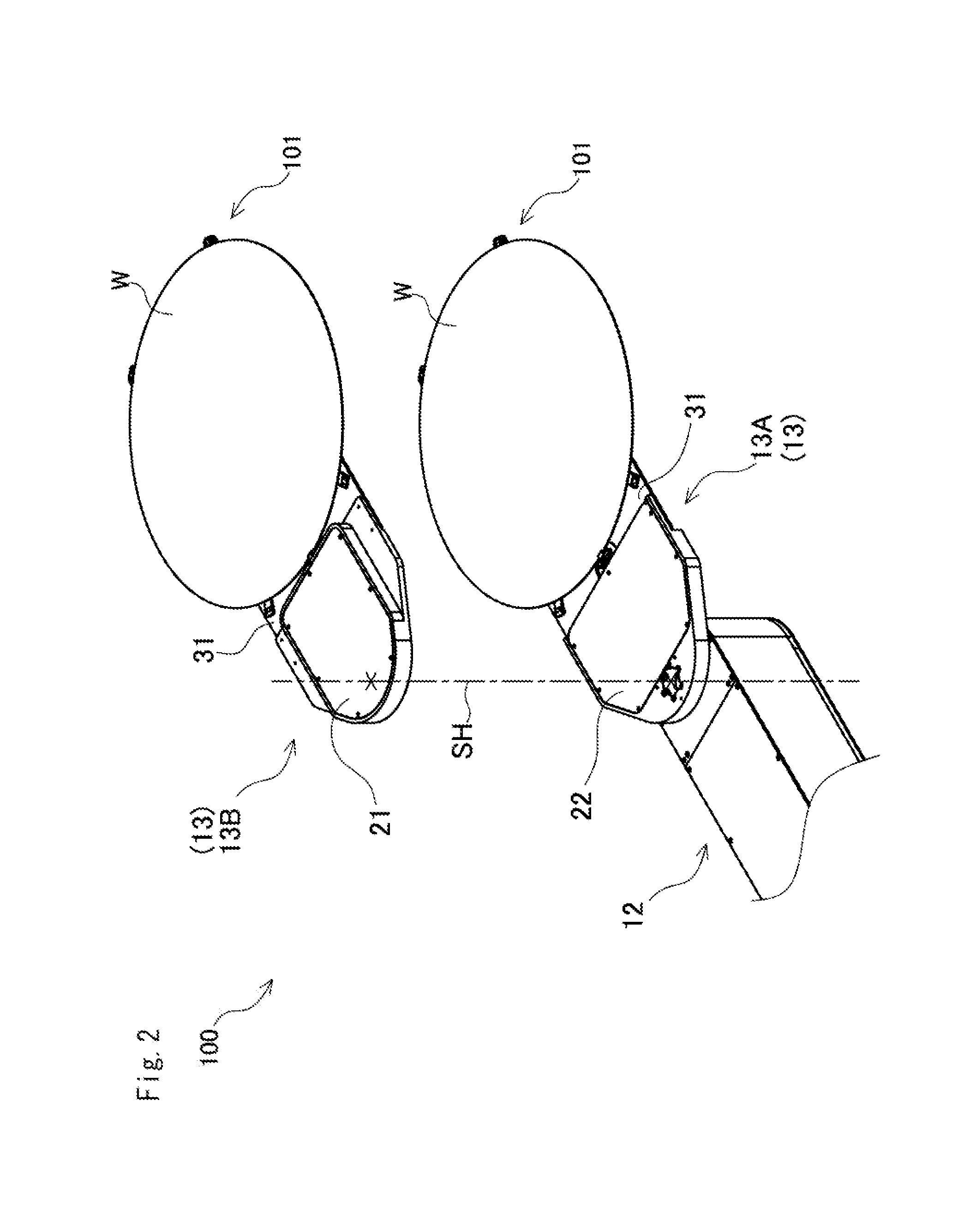
[0042]As shown in FIG. 1, this workpiece conveying robot 100 is configured as a robot of a horizontal joint type having three joints, and relative to a base 4, a first arm element 11, a second arm element 12, and a hand portion 13 are provided so as to be sequentially relatively ...
PUM
 Abstract
Description
Claims
Application Information