
Thin-Sheet Clinch Fastener

a clinch and thin sheet technology, applied in the direction of threaded fasteners, fastening means, screws, etc., can solve the problems of manufacturing methods beginning to fail

Inactive Publication Date: 2017-04-27
PEM MANAGEMENT INC
View PDF1 Cites 4 Cited by
  • Summary
  • Abstract
  • Description
  • Claims
  • Application Information

AI Technical Summary

Benefits of technology

The thin-sheet clinch fastener has the following advantages: it can be used on very thin metal sheets and is smaller in size compared to traditional clinch fasteners. It creates a new mode of retention by making a conical shape in the metal panel, which results in stronger holding power compared to traditional fasteners. The reverse configuration of the cone creates compressive retaining forces, which are stronger than shear retaining forces.

Problems solved by technology

Once the panel becomes very thin, for example in the range of 0.008″ thick, manufacturing methods begin to fail since the features necessary for clinching require a range of tolerance that is very difficult (if at possible at all) impossible to meet and still be functional.

Method used


Image

  • Thin-Sheet Clinch Fastener
  • Thin-Sheet Clinch Fastener
  • Thin-Sheet Clinch Fastener

Examples


Embodiment Construction

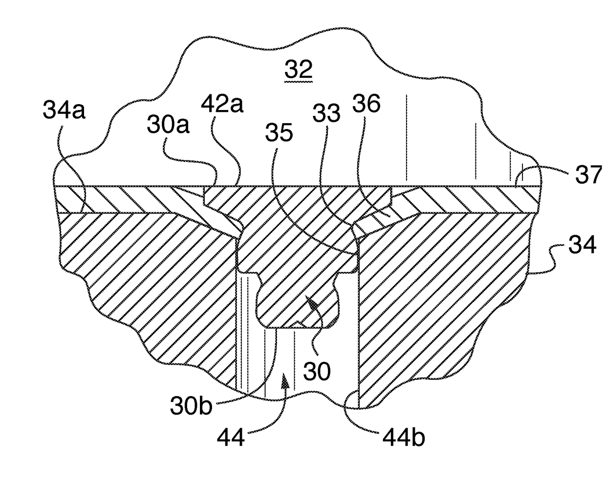
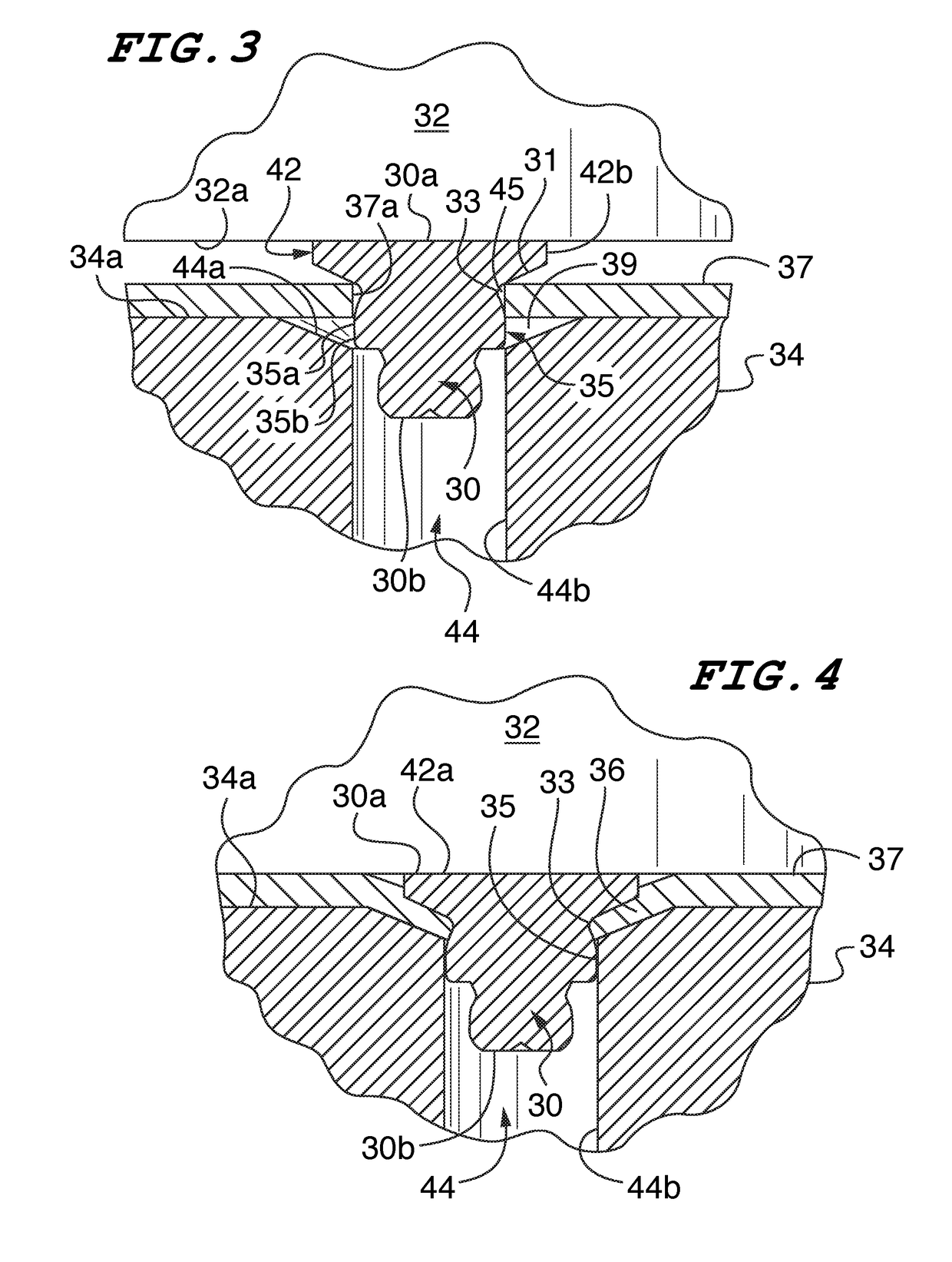
[0017]A clinch fastener in accordance with a preferred embodiment of the invention is shown in FIGS. 3-5 and is designated by reference numeral 30. The clinch fastener 30 has a circular cross-section and generally comprises a head 42, a displacer 31, an undercut 33, and a shank 35 arranged sequentially from the head end 30a to the distal free end 30b of the fasteners. While these structures have the same names as the structures of prior art clinch fasteners, applicant's fastener captivates differently and fails differently than prior art clinch fasteners.

[0018]The head 42 has a circular, planar top surface 42a and an annular rim 42b. The top surface is orthogonal to a central, longitudinal axis. In the preferred embodiment shown in FIGS. 3-5, the bottom surface of the head is skew to the central axis and forms a tapered shoulder 31. The shoulder 31 tapers inwardly extending from the head end 30 the distal free end 30b. In a preferred embodiment, the taper of the shoulder is linear a...


PUM


Abstract

A unitary metal clinch fastener comprises a top most head and an inwardly tapered shoulder extending axially downwardly from and located immediately below the head. The shoulder has an outwardly-facing angled surface for deforming material of a metal panel into which the fastener is installed. An outwardly-flared shank is located below the shoulder. The shank has an upwardly-facing outer surface adapted to engage an edge of an installation hole in the panel. A neck of reduced diameter is located at a junction of the shank and the shoulder and is adapted to engage the edge of the installation hole to attach the fastener to the panel. The panel installation hole is centered in a conical recessed section of the panel and is convergently-angled downwardly with the edge of the hole abutting the upwardly-facing surface of the shank.

Description

RELATED APPLICATIONS[0001]This is a non-provisional patent application of U.S. provisional patent application No. 62 / 245,079 entitled “Thin Sheet Clinching Fastener” filed on Oct. 22, 2015, priority from which is hereby claimed.FIELD OF THE INVENTION[0002]The present invention relates to clinch fasteners that are especially useful for installation and use on thin-sheet metal panels.BACKGROUND OF THE INVENTION[0003]Clinch fasteners are well known for permanently affixing a hardened fastener to a sheet metal panel. Clinch fasteners typically include a head 13, a displacer 14, an undercut 15 and a shank 19 arranged sequentially from the head end to the distal free end of the fastener such as shown in FIG. 1. When inserted and pressed into an aperture in a sheet metal panel 17, the displacer deforms and pushes metal surrounding the aperture into the undercut such as shown in FIG. 2. The undercut is formed between the displacer and the shank, and has a diameter less than the diameter of ...

Claims


Application Information

Patent Timeline
Patent Type & Authority Applications(United States)
IPC IPC(8): F16B19/06F16B37/06
CPCF16B37/065F16B19/06F16B5/04F16B35/06F16B37/068
Inventor MALONEY, MICHAEL J.
Owner PEM MANAGEMENT INC
Learn More