Image pickup apparatus with air cooling unit

a pickup apparatus and air cooling technology, applied in the field can solve the problems of increased cost, insufficient rigidity of image pickup apparatuses of this type, and difficulty in achieving a sufficient heat radiation effect, and achieve excellent rigidity and heat radiation efficiency.

Active Publication Date: 2014-02-27
CANON KK
View PDF3 Cites 14 Cited by
  • Summary
  • Abstract
  • Description
  • Claims
  • Application Information

AI Technical Summary

Benefits of technology

[0006]The present invention provides an image pickup apparatus that is excellent in rigidity and in heat radiation efficiency.

Problems solved by technology

As a result, it becomes difficult to achieve a sufficient heat radiation effect by the above-described heat radiation structure where the air inlet port is connected to the cooling fan through the ventilation duct.
In addition, image pickup apparatuses of this type do not have a sufficient rigidity against external compression and torsion.
To increase the rigidity, reinforcing members must be added, resulting in increased cost.

Method used


Image

  • Image pickup apparatus with air cooling unit
  • Image pickup apparatus with air cooling unit
  • Image pickup apparatus with air cooling unit

Examples


first embodiment

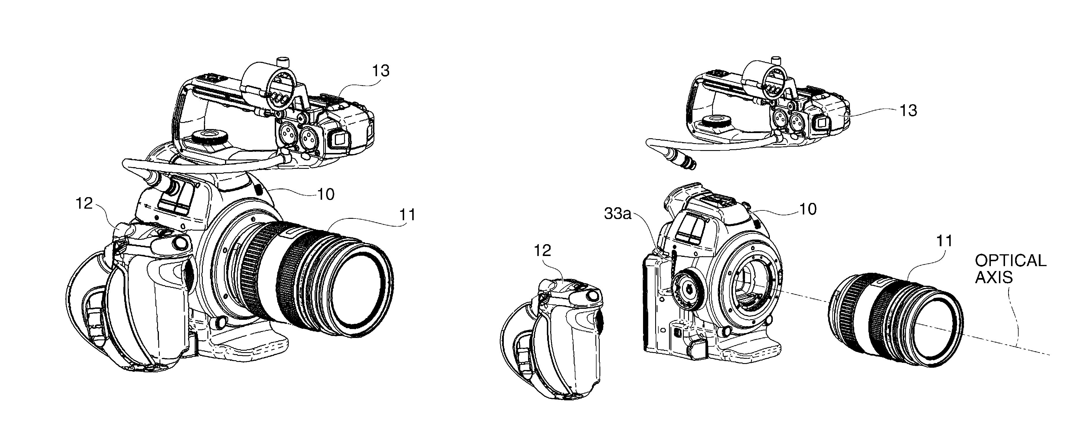
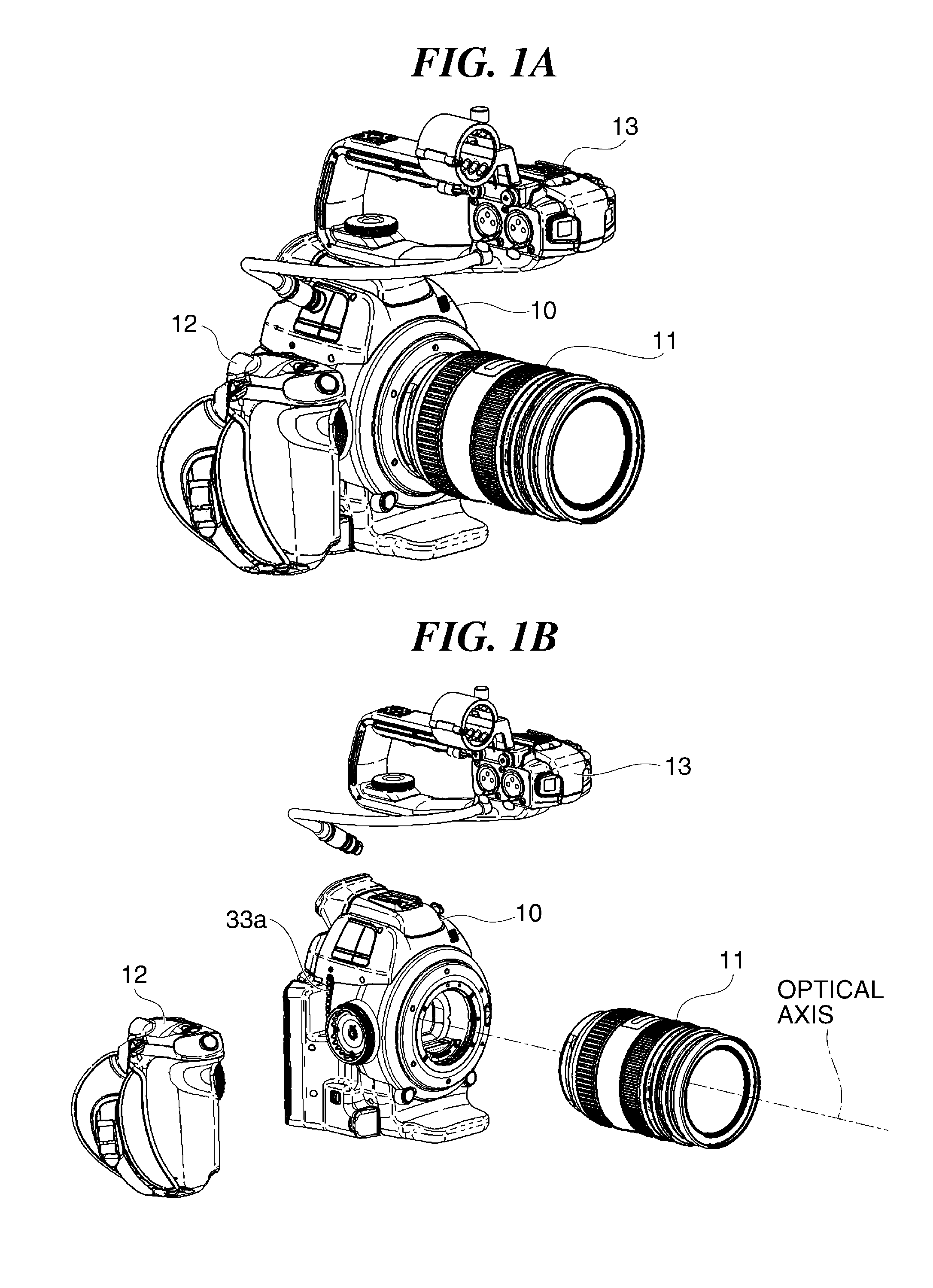
[0048]FIG. 1A shows in external perspective view a digital camera serving as an image pickup apparatus according to a first embodiment of this invention, and FIG. 1B shows in perspective view a state where a lens barrel, a grip, and a handle of the digital camera are detached from a camera main unit.

[0049]As shown in FIGS. 1A and 1B, the digital camera of this embodiment has the camera main unit 10 (apparatus main unit) to which the lens barrel 11, grip 12, and handle 13 can be detachably mounted. Each of the lens barrel 11, grip 12, and handle 13 has an input / output unit (e.g., connectors such as a jack), and is electrically connected to the camera main unit 10 through the input / output unit when mounted to the camera main unit 10.

[0050]FIGS. 2A and 2B respectively show the camera main unit 10 in left side view and in front view. The camera main unit 10 is provided with a power source dial 24, operation buttons 25, an air outlet port 26, and a view finder 27 which are shown in FIG. ...

second embodiment

[0108]Next, with reference to FIGS. 27 to 29, a description will be given of a digital camera serving as an image pickup apparatus according to a second embodiment of this invention. As compared to the first embodiment, this embodiment differs only in the arrangement of the image pickup unit. In the following, elements that are the same as those in the first embodiment will be denoted by the same reference numerals, and a description thereof will be omitted.

[0109]FIG. 27 shows in perspective view the arrangement of the main circuit board 36, heat sink-cum-duct 50, elastic member 53, centrifugal fan 40, and image pickup unit 200. FIG. 28 shows a state where the main circuit board 36, heat sink-cum-duct 50, and centrifugal fan 40 are assembled together, and FIG. 29 shows in top view the assembly shown in FIG. 28.

[0110]In the first embodiment, the image pickup unit 20 and the centrifugal fan 40 are disposed on the optical axis so as to be nearly parallel to each other. On the other han...


PUM


Abstract

An image pickup apparatus that is excellent in rigidity and in heat radiation efficiency. The image pickup apparatus has a heat sink-cum-duct disposed between a pair of cover members that constitute left and right exteriors of an apparatus main unit and that are fixed to the heat sink-cum-duct. The heat sink-cum-duct has an opening formed to correspond to an air inlet port of an air cooling fan and has a plurality of fins, and sucks air through the opening from the outside. The sucked air is guided to the air inlet port of the cooling fan through a ventilation path defined by the plurality of fins.

Description

BACKGROUND OF THE INVENTION[0001]1. Field of the Invention[0002]The present invention relates to an image pickup apparatus such as a digital camera or a digital video camera mounted with an air cooling unit.[0003]2. Description of the Related Art[0004]An image pickup apparatus such as digital video camera mounted with an air cooling unit has been known. For example, there has been proposed a video camera that has a cooling fan disposed inside an exterior casing of the video camera (Japanese Laid-open Patent Publication No. 2009-296469). In this proposal, an air inlet port formed in the exterior casing of the video camera is connected through a ventilation duct to the cooling fan, thereby sucking a sufficient amount of air for heat radiation into inside the video camera to efficiently cool camera component parts that generate heat.[0005]In recent image pickup apparatuses such as digital cameras, an amount of heat generated in a circuit board increases with enhancement of apparatus fu...

Claims


Application Information

Patent Timeline
Patent Type & Authority Applications(United States)
IPC IPC(8): H04N5/225
CPCH04N5/2252H04N23/51H04N23/54G02B7/028
Inventor KAWAMURA, AYUMU
Owner CANON KK
Why Eureka
Try Eureka