
Magnetic circuit for loudspeaker and loudspeaker using the same

a technology of magnetic circuit and loudspeaker, which is applied in the direction of transducer details, electrical transducers, electrical apparatus, etc., can solve the problems of unstable dimensions of sintering, difficult application, and inability to apply cutting work, so as to achieve good dimensional accuracy and improve dimensional accuracy. , the effect of efficient magnetic circui

Inactive Publication Date: 2014-02-27
PANASONIC INTELLECTUAL PROPERTY MANAGEMENT CO LTD
View PDF1 Cites 9 Cited by
  • Summary
  • Abstract
  • Description
  • Claims
  • Application Information

AI Technical Summary

Benefits of technology

The present invention provides a smaller, thinner, and lighter magnetic circuit for a loudspeaker by eliminating wasted space inside the magnetic circuit caused by poor dimensional accuracy of a sintered magnet. This is achieved by using a bonded magnet with good dimensional accuracy obtained through injection molding, which allows the same dimensions to be set for the magnet and the top plate. A protrusion of the magnet toward the outside can be eliminated to downsize the loudspeaker and improve magnetic efficiency. The specific gravity of a bonded magnet can be lower than that of a conventional magnet according to the proportion of resin, making the magnetic circuit lighter. This structure prevents a gap failure, improves magnetic efficiency, and provides a smaller, thinner, and lighter magnetic circuit.

Problems solved by technology

However, the sintering is a manufacturing method unstable for dimensions.
However, since post-processing, such as cutting work, is difficult to be applied to the inner diameter and outer diameter of magnets 1 and 1A, cutting work is not applied.
Accordingly, the accuracy of inner diameter and outer diameter of magnets 1 and 1A are extremely poor.

Method used


Image

  • Magnetic circuit for loudspeaker and loudspeaker using the same
  • Magnetic circuit for loudspeaker and loudspeaker using the same
  • Magnetic circuit for loudspeaker and loudspeaker using the same

Examples


Embodiment Construction

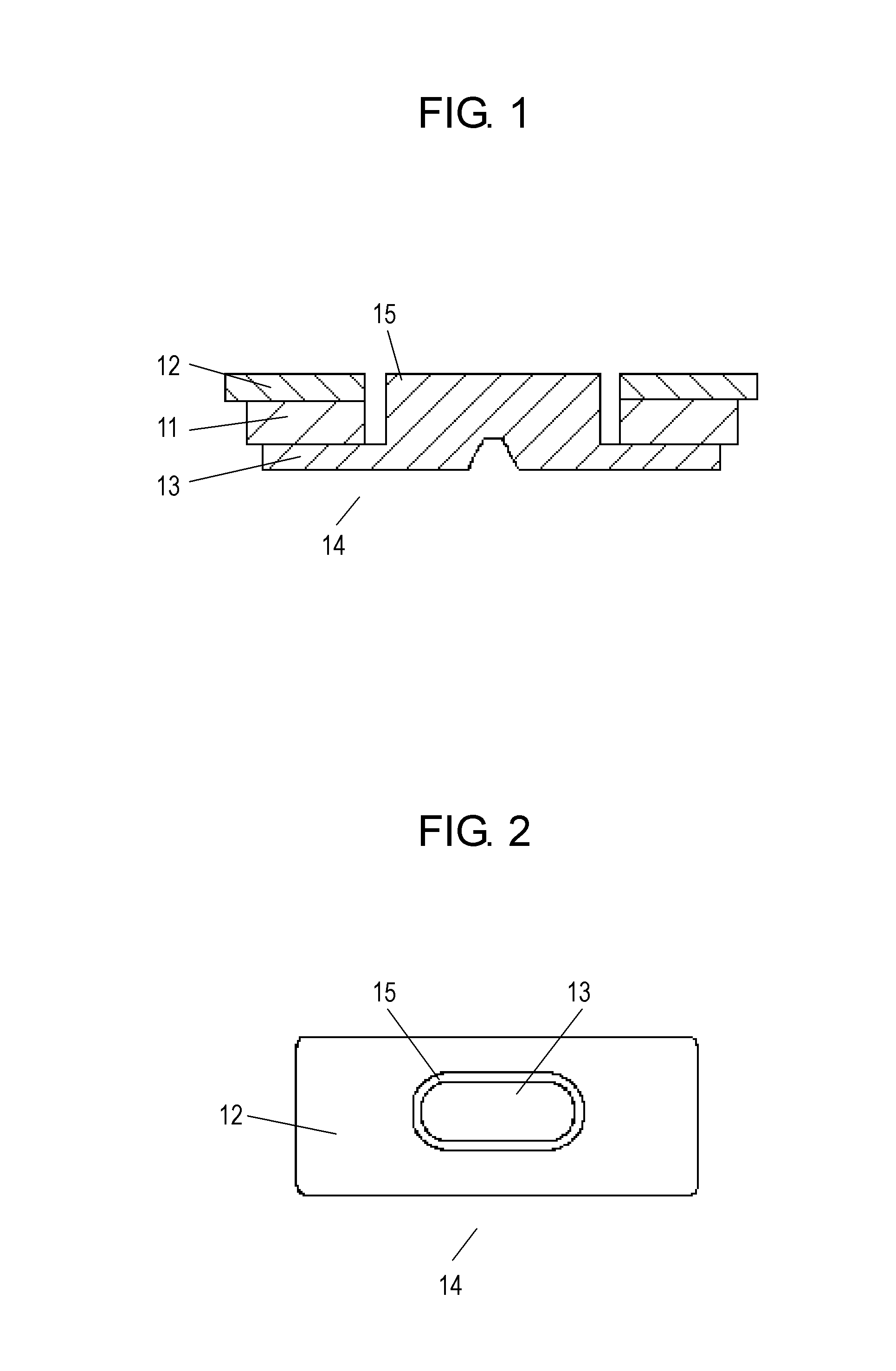
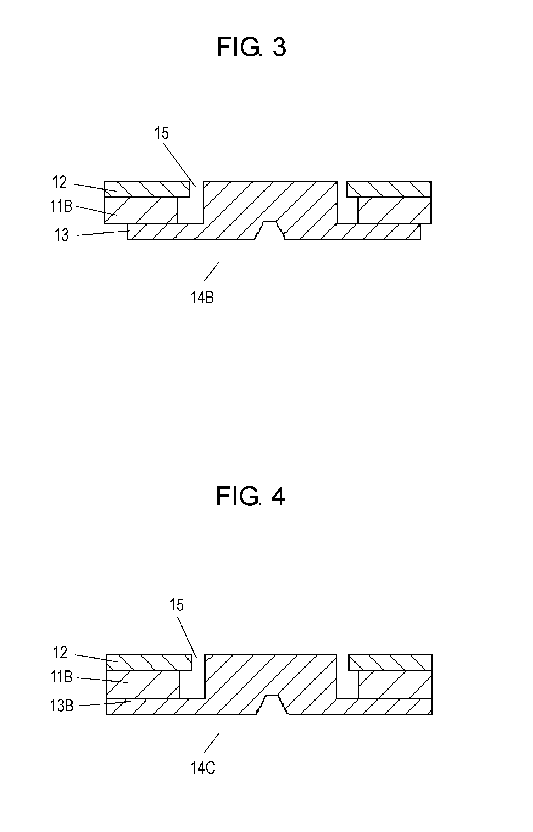
[0057]FIGS. 1 to 29 are sectional views and plan views of magnetic circuits for a loudspeaker according to exemplary embodiment of the present invention.

[0058]FIGS. 1 to 19 are sectional views and plan views of outer-magnet-type magnetic circuits for a loudspeaker according to the embodiment of the invention. FIGS. 20 to 29 are sectional views of inner-magnet-type magnetic circuits for a loudspeaker according to the embodiment of the present invention.

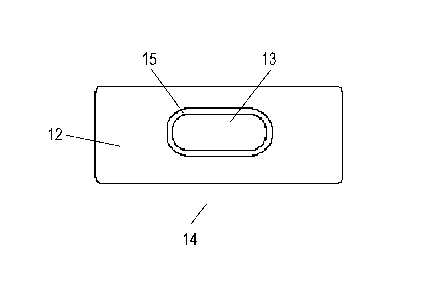
[0059]FIG. 1 is a sectional view of a slim magnetic circuit. As shown in FIG. 2, a plan view of the magnetic circuit, the magnetic circuit has a rectangular outer shape and a magnetic gap having a racetrack shape.

[0060]However, the present invention is not limited to this shape. The magnetic circuit may have a circular outer shape or a circular magnetic gap. These shapes also provide the same effect. As shown in FIGS. 1 and 2, magnet 11 is sandwiched between top plate 12 and bottom plate 13 to configure outer-magnet-type magnetic circu...


PUM


Abstract

A magnetic circuit for a loudspeaker includes a magnet and a top plate. The magnet is made of a bonded magnet. The magnet and the top plate are configured to satisfy at least one of conditions that an inner diameter of the magnet is identical to an inner diameter of the top plate, and that an outer diameter of the magnet is identical to an outer diameter of the top plate. This configuration eliminates a wasted space inside the magnetic circuit, and protrusion of the magnet to outside, hence providing a light and efficient magnetic circuit.

Description

TECHNICAL FIELD[0001]The present invention relates to a magnetic circuit for a loudspeaker and a loudspeaker using the magnetic circuit that is employed in products for vehicles, video, audio, and mobile communications.BACKGROUND ART[0002]FIGS. 32 and 33 are sectional views of a conventional magnetic circuit for loudspeaker. Conventionally, the magnetic circuit includes a magnet and at least a top plate.[0003]Outer-magnet-type magnetic circuit 4 shown in FIG. 32 further includes bottom plate 3 in addition to magnet 1 and top plate 2.[0004]Inner-magnet-type magnetic circuit 4A shown in FIG. 33 further includes yoke 3A in addition to magnet 1A and top plate 2A.[0005]Magnetic gaps 5 and 5A are magnetic spaces where a voice coil inserted therein vertically vibrates upon receiving a magnetic force when magnetic circuit 4 or 4A is used in a loudspeaker. Magnetic gaps 5 and 5A are parts that require extremely high accuracy. Dimensions of magnetic gaps 5 and 5A and vertical dimensions of ma...

Claims


Application Information

Patent Timeline
Patent Type & Authority Applications(United States)
IPC IPC(8): H04R3/00
CPCH04R3/00H04R9/025H04R9/06H04R2499/11H04R2499/13H04R2499/15H04S2420/01H04R31/006
Inventor KUZE, MITSUKAZUKOURA, SATOSHITSUCHIYA, GOROITANO, TETSUSHI
Owner PANASONIC INTELLECTUAL PROPERTY MANAGEMENT CO LTD
Learn More