BEST WAY OF CARRYING OUT THE INVENTION
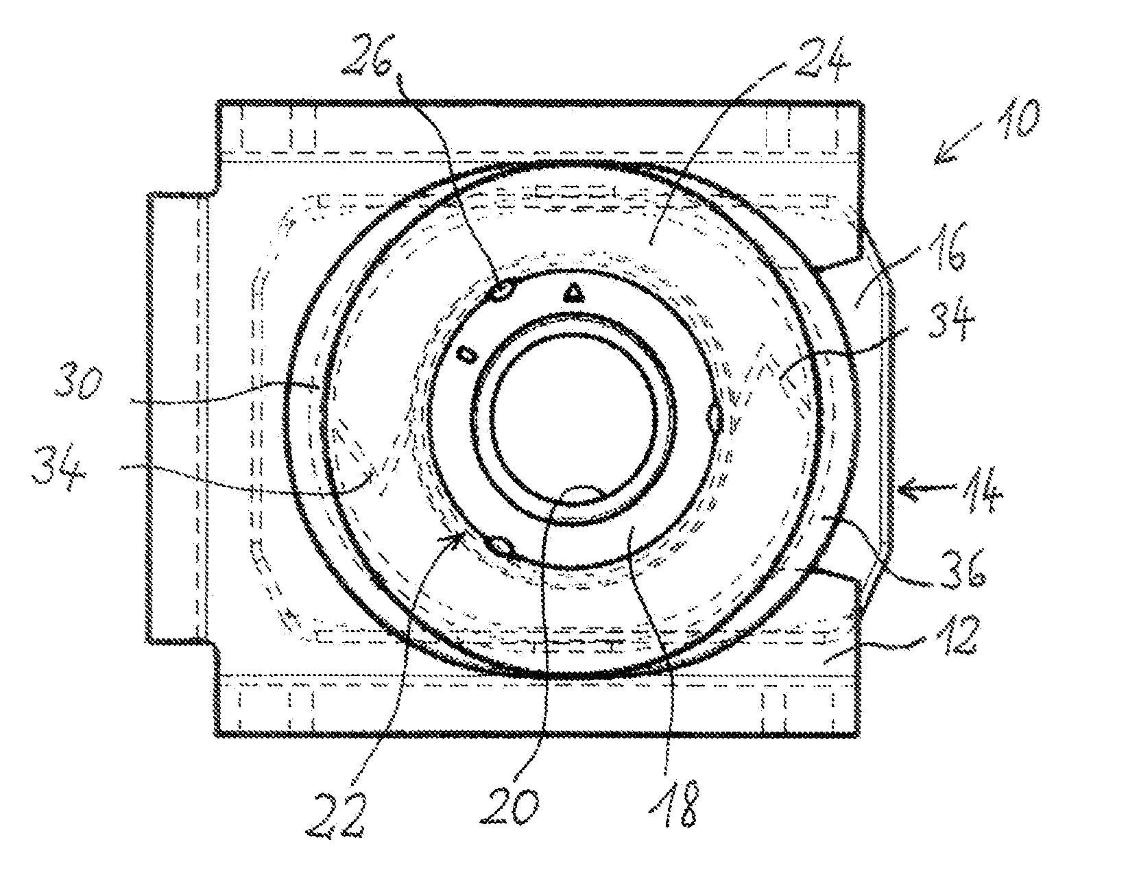
[0023]FIG. 1 shows a cage nut 10 according to the invention from the front, that is to say viewed from the direction in which the screw bolt is usually screwed into the cage nut 10.
[0024]Components of the cage nut 10 which are not directly visible are shown here in broken lines.
[0025]As is conventional, the nut comprises a rectangular cage 12 which can be welded to the component to which the cage nut 10 according to the invention is to be attached. At the front, the cage 12 has a substantially circular opening which is broken open towards the side on one side, namely on the side on which a nut body 14 can later be inserted. The nut body 14 in such case has an enlarged flange 16 as holding element and a hollow-cylindrical shoulder 18 with an internal thread 20. The hollow-cylindrical shoulder 18 in this case extends with its
[0026]axial direction in the direction of viewing of FIG. 1, that is to say, in the direction in which a screw bolt can be screwed into the cage nut according to the invention. The flange 16 extends perpendicular to this direction and has the shape of a rectangle with bevelled corners. According to the invention, a spacer element 22 is placed on the hollow-cylindrical shoulder such that it is likewise located within the opening of the cage 12. The spacer element 22 will be described in greater detail below with reference to FIGS. 2 and 3. In FIG. 1, in contrast, it can be seen how the spacer element 22 is inserted between the hollow-cylindrical shoulder 18 of the flange 16 in the opening of the cage 12. In order to secure the nut body 14 in the cage 12, there is provided outside the cage 12 a locking washer 24 which surrounds the hollow-cylindrical shoulder 18 of the nut body 14 and is fixed there by three equally spaced-apart punch marks 26. The external diameter of the locking washer 24 in this case is at least somewhat greater than the diameter of the opening in the cage 12. According to the invention, there is however also the possibility of the nut body 14 being held in the cage 12 exclusively by the spacer element 22. With such a design, the spacer element itself is then directly secured by the punch marks 26 on the hollow-cylindrical shoulder 18 of the nut body 14.
[0027]The spacer element 22 in such case is supported on the inner walls of the cage 12. It will be described in greater detail below with reference to FIGS. 2 and 3.
[0028]FIG. 2 shows the spacer element 22, which in the present embodiment is formed as an injection-moulded plastics part. It comprises an inner ring 28 and an outer ring 30 which is spaced apart therefrom but arranged coaxially thereto. The outer ring 30 in this case is matched to the shape of the opening already when it is manufactured, here by being formed flattened on two opposite sides.
[0029]The inner ring 28 and the outer ring 30 of the spacer element 22 are elastically connected together by two spring elements 34. Alternatively, a different number of spring elements, for example 3 or 4, or even only one spring element, may also be provided.
[0030]Here, the spring elements 34 are arranged such that they connect the inner and the outer spacer ring 28 and 30 exactly between the flattened sections 32. In this manner, a particularly large amount of play is available for the spring elements 34.
[0031]According to the invention, here the spring elements 34 are produced in one piece with the two rings 28 and 30 of the spacer element 22 in an injection-moulding process. The spring elements 34 in this case are in the form of strips bent in a V-shape, the bend running parallel to the axial direction of the internal thread 20. In this way, the spring elements 34 have a particularly great degree of elasticity perpendicular to the axial direction of the internal thread 20, and particularly great stability in the axial direction.
[0032]The inner ring 28 is formed as a short hollow cylinder which is coaxial to the hollow-cylindrical shoulder 18. In FIGS. 2 and 3 it extends further into the cage 12 than the other parts of the spacer element 22. In this manner, the inner ring 28 at the same time serves as a spacer in the axial direction which prevents the flange 16 from touching and/or coming into electrical contact with the cage 12. In this manner, the cage nut 10 according to the invention at the same time is an electrically insulating cage nut, which offers great advantages for example in the electrophoretic painting of components already provided with these cage nuts. Furthermore, it is thus ensured that there is always a sufficient gap between the flange 16 and the cage 12, so that these two components cannot stick together because of paint being sucked in due to a capillary effect.
[0033]FIG. 3 further clearly shows that the outer ring 30 of the spacer element 22 has an edge 36 extending outwards on its end which faces the screwing-in side of the cage nut 10. With this edge 36, the spacer element 22 is supported on the outer side of the front wall of the cage 12.
[0034]An arrangement of the spring elements 34 is particularly preferred in which the one spring element 34 in FIG. 1 points upwards with its edge and the other points downwards with its edge.
[0035]The cage 12 and nut body 14 in this case are preferably made of steel. However, also any other metal, and also a non-metallic material, may be used. In order to maintain the electrical insulation between the cage 12 and nut body 14, the locking washer 24 is preferably produced from an electrically insulating material, in particular plastics material. In such case, production likewise as an injection-moulded plastics part is recommended.
[0036]FIGS. 4, 5, 6 and 7 show the different excursions of the cage nut according to the invention for compensating for existing manufacturing tolerances. In these figures, the excursions of the spring elements 34 in each case are very clearly recognisable.
[0037]The cage nut 10 is assembled such that first the spacer element 22 is inserted into the opening of the cage 12 from the front, and then the nut body 14 is inserted into the cage 12 from the rear, with the hollow-cylindrical shoulder 18 being simultaneously pushed into the inner ring 28. The spacer element 22 is then seated in the opening of the cage 12, the edge 36 being supported externally on the front wall of the cage 12. Additionally, then the locking washer 24 can be placed on the hollow-cylindrical shoulder 18.
[0038]With the fixing of the inner ring 28 of the spacer element 22 or of the locking washer 24 on the shoulder 18 by punch marks, the mounting is then finished.