Device to hold a work spindle

Inactive Publication Date: 2012-03-15
JAKOB ANTRIEBSTECHN
View PDF5 Cites 4 Cited by
  • Summary
  • Abstract
  • Description
  • Claims
  • Application Information

AI Technical Summary

Benefits of technology

[0005]The goal of the invention is to create a device to hold a motor-driven work spindle in a housing of a processing machine, which makes possible an optimal collision pro

Problems solved by technology

If the work spindle is displaced from the operating position as a result of a co

Method used


Image

  • Device to hold a work spindle
  • Device to hold a work spindle
  • Device to hold a work spindle

Examples


Example

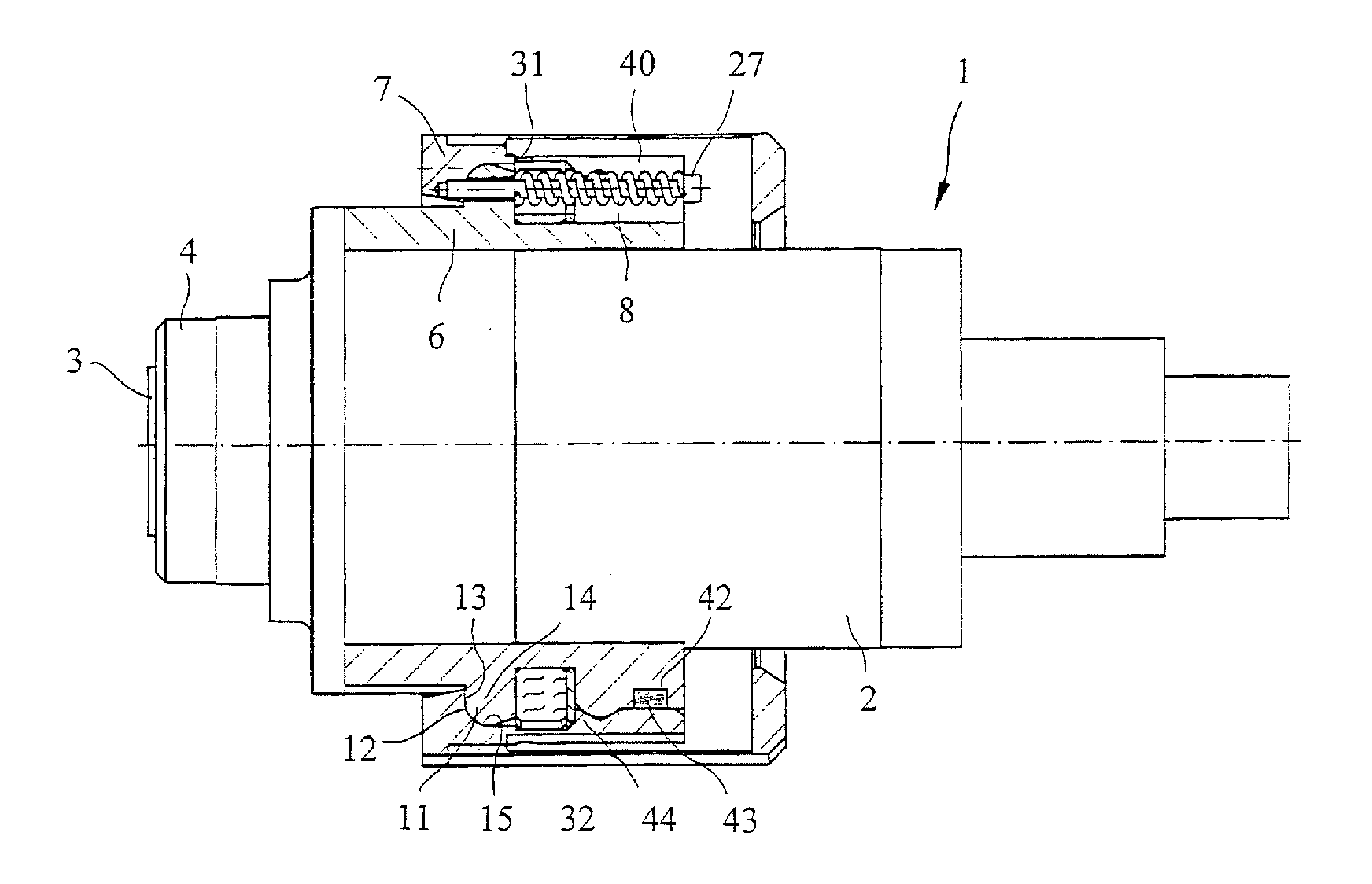
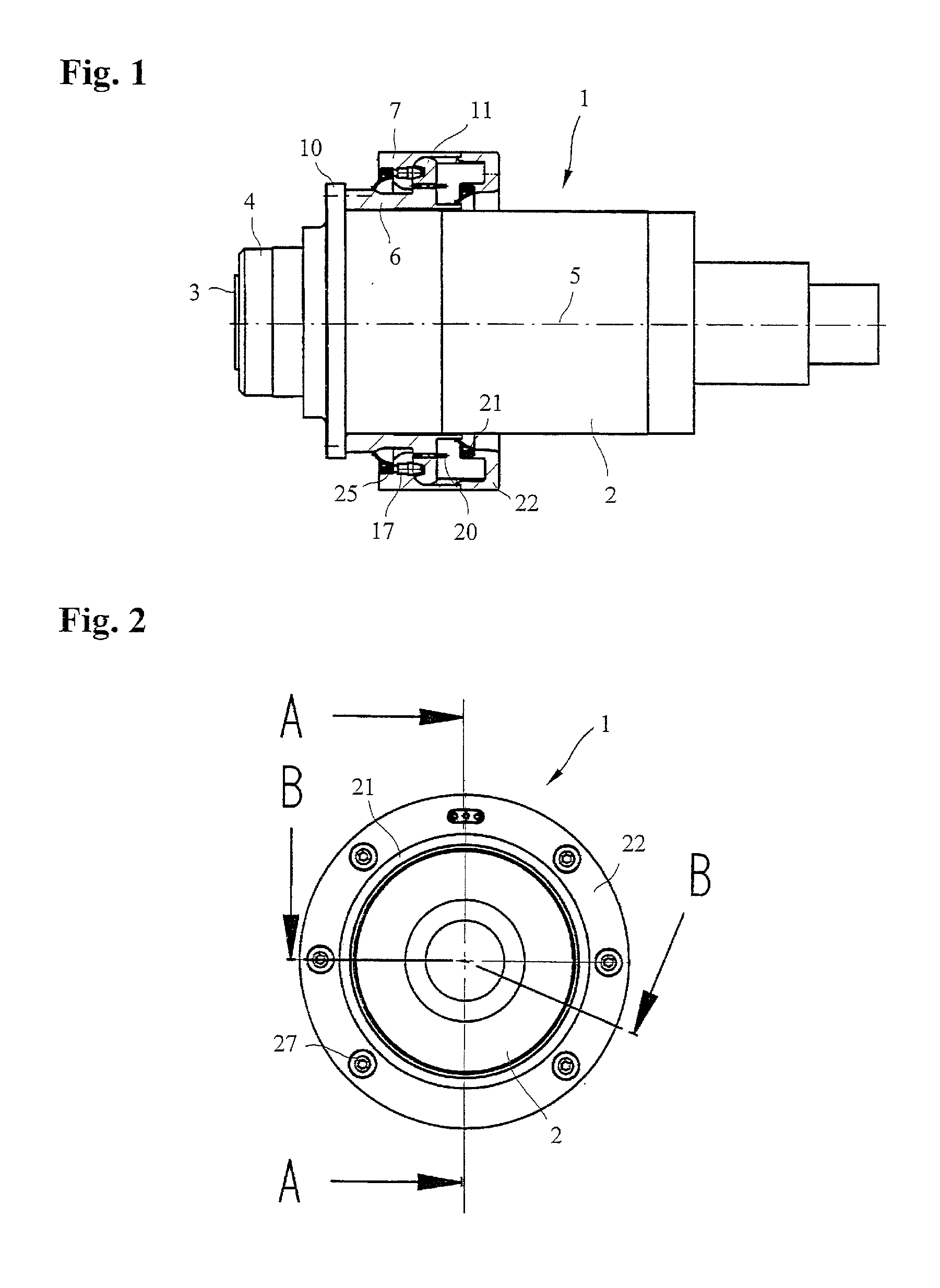
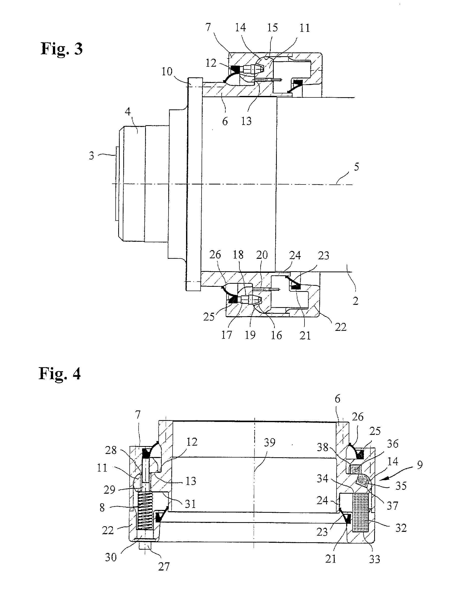
[0026]FIGS. 1 and 2 show a device to hold a work spindle 1, constructed here as a motor spindle, in a housing of a tool machine, which is not depicted, or another processing machine. The housing can, for example, be a part of a feed carriage, a machine frame, or another part of a tool machine. The work spindle 1, constructed as a motor spindle, contains a spindle housing 2, in which a spindle 4, provided with a tool holder 3, is supported, via a bearing, which is not depicted, in such a manner that it can rotate around a middle axis 5. The work spindle 1, constructed as a motor spindle, also has a drive motor, located in the spindle housing 3, in a manner which is, in fact, known, wherein the spindle 4 forms the rotor of the drive motor. The work spindle 1 can also have an integrated clamping device with a detachment unit, an internal lubricator supply, a cooling, and so forth, and thus forms a complete drive unit, which is used, above all, on milling or grinding machines, as a driv...


PUM

PropertyMeasurementUnit
Forceaaaaaaaaaa
Angleaaaaaaaaaa
Distanceaaaaaaaaaa

Abstract

The invention concerns a device to hold a motor-driven work spindle (1) in a housing of a processing machine with an outside ring (7) and an inside ring (6), arranged within the outside ring (7), so that it can be displaced and tilted axially, to hold the work spindle (1), wherein the inside ring (6) is pretensioned with respect to the outside ring (7), in an elastically resilient manner in the axial direction, by at least one pretension element (8), and wherein the inside ring (6) is held in an operating position within the outside ring (7) by a holding device with a prespecified holding force. The holding device is designed as a magnet arrangement (9) with at least one magnet (35, 36; 43), arranged in the inside ring (6) and/or the outside ring (7), for the creation of a magnetic holding force.

Description

CROSS REFERENCE TO RELATED APPLICATIONS [0001]This application claims priority under 35 U.S.C. §119 to German Patent Application No. 10 2010 045 113.4 filed Sep. 13, 2010, the entire contents of which are incorporated herein by reference.Field of the Invention[0002]The invention relates to a device to hold a motor-driven work spindle in a housing of a processing machine.BACKGROUND OF THE INVENTION[0003]In machine tools with motor-driven work spindles, enormous impact forces act on the work spindles for a brief period of time with tool collisions at high feed speeds. In order to ensure protection for impact-sensitive components during collisions, special safety concepts for making possible a deflection of work spindles are used.[0004]From DE 10 2007 032 498 A1, a safety device for a motor spindle is known, arranged in a housing, with an outside ring and an inside ring arranged axially, so it can be displaced and tipped, within the outside ring, to hold the motor spindle. The inside r...

Claims


Application Information

Patent Timeline
IPC IPC(8): B23Q5/54
CPCY10T82/2562B23Q5/58Y10T409/309352B23Q11/04Y10T82/2561B23Q1/70
Inventor JAKOB, LUDWIGWOERN, ARNO
Owner JAKOB ANTRIEBSTECHN
Why Eureka
Try Eureka