
System and method for the powering and fault protection of remote telecommunications equipment

Active Publication Date: 2005-03-10
CIENA
View PDF9 Cites 7 Cited by
  • Summary
  • Abstract
  • Description
  • Claims
  • Application Information

AI Technical Summary

Benefits of technology

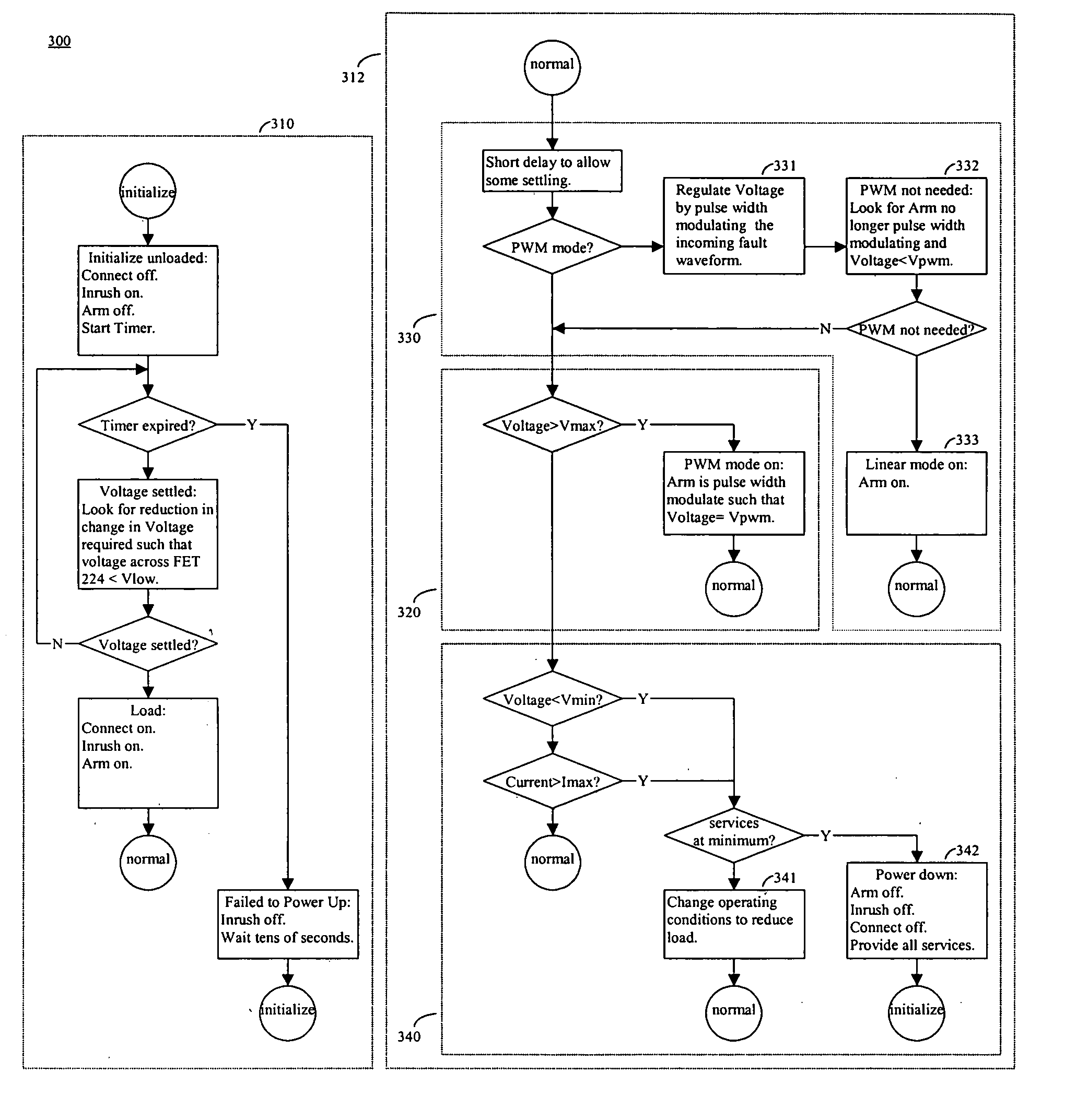
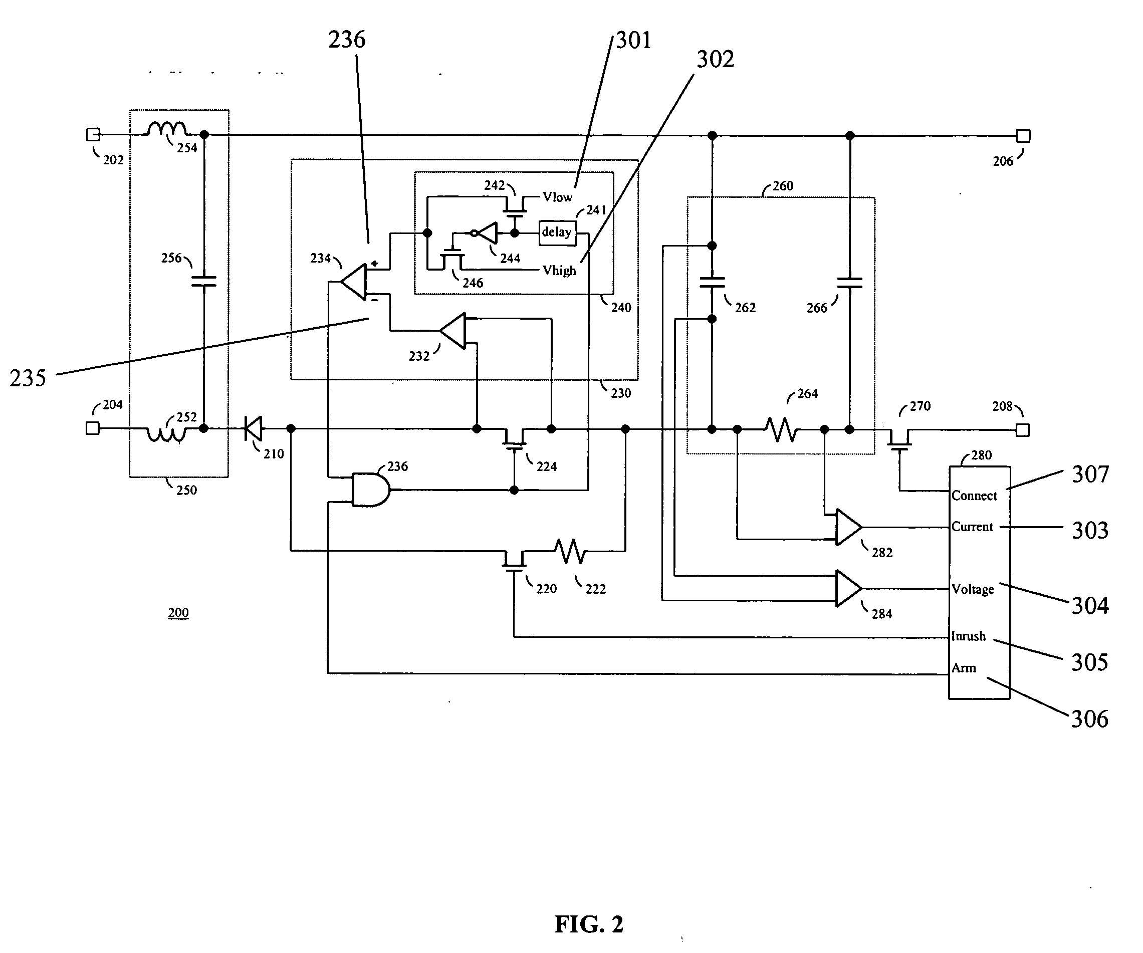
[0024] Preferably, the processor is further adapted to, when the voltage signal exceeds a predetermined maximum voltage: reset the inrush signal to open the inrush switch and disconnect the inrush resistor; and, modulate the arm signal, thereby reducing the voltage provided to the telecommunications equipment.
[0032] Advantageously, the processor allows for flexibility to optimally configure the protection circuit for various fault events. These fault events are sensed by the processor through its current and voltage analog inputs, the data from which is processed to control the processor's connect, inrush, and arm digital outputs such that the telecommunications equipment connected to the protection circuit is subject to minimum stress through rapid response to the fault event.

Problems solved by technology

In telecommunications systems, some equipment may be located in a remote location where accessing a power source to power the equipment is neither economical nor desirable due to cost or marketing considerations.
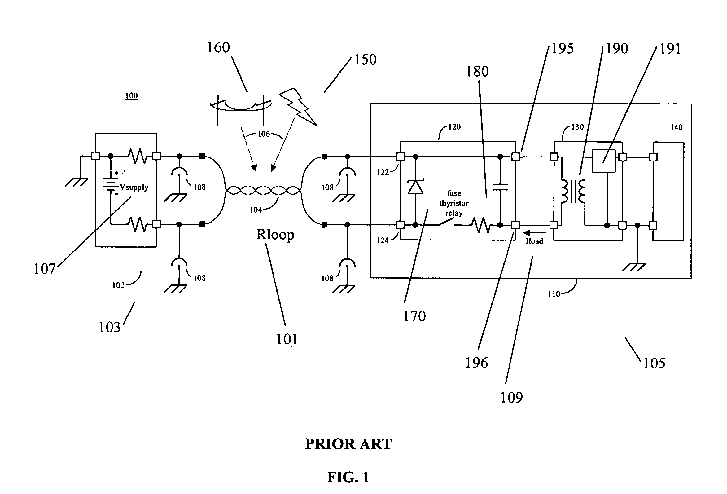
However, these systems are not applicable to subscriber loops that are used for the loop powering of remote equipment, in that the series impedance of electronics on each end of the subscriber loop utilized for loop powering, typically a few ohms, is considerably lower than the series impedance of the electronics on a subscriber loop used for mainstream applications, typically 100 ohms or more.
However, such equipment cannot be earth referenced and typically prevents the conduction of current to earth for voltages within the primary protector activation voltage range.
Thus, protection circuits for electronics that sink energy from a subscriber loop 104 and that form the power supply of remotely powered electronics equipment 110 are challenging to design effectively.
Furthermore, standards bodies are now requiring more stringent testing, thus solutions based on thyristors have greater difficulty achieving compliance.
However, relays being mechanical are prone to wear and tear.
These protection circuits are thus expensive to deliver and maintain and result in interruption of service when faults occur.
Even new generation remote telecommunications equipment that is loop powered with copper subscriber loops, and that relies on optical fiber for all transmission, is subject to disruption of service if the remote equipment 110 is susceptible to outages due to fault conditions that affect the copper subscriber loop (i.e., but not the optical fiber).
This results in increased costs for capital equipment and maintainance.

Method used


Image

  • System and method for the powering and fault protection of remote telecommunications equipment
  • System and method for the powering and fault protection of remote telecommunications equipment
  • System and method for the powering and fault protection of remote telecommunications equipment

Examples


Embodiment Construction

[0038] In the following description, numerous specific details are set forth to provide a thorough understanding of the invention. However, it is understood that the invention may be practiced without these specific details. In other instances, well-known structures and / or processes have not been described or shown in detail in order not to obscure the invention.

[0039] Referring again to FIG. 1, in this environment 100 and in the presence of the illustrated external protection electronics 108, a number of fault conditions may be presented at the input nodes 122 and 124 of the remote equipment 110.

[0040] When lightning 150 strikes in close proximity to the subscriber loop 104, current is induced in the subscriber loop 104 which may develop a potential difference between nodes 122 and 124 that exceeds the activation voltage of the primary protectors 108. Due to the independent nature of the primary protectors 108, one protector may change from open circuit to closed circuit before t...


PUM


Abstract

A protection circuit for telecommunications equipment powered remotely through a twisted pair subscriber loop, comprising: a charge storage circuit, coupled to the subscriber loop through an arm switch in parallel with an inrush resistor, for storing charge received from the subscriber loop, the charge storage circuit coupled to the telecommunications equipment for providing the charge thereto; a fault detection circuit for setting a first signal during a period of normal operation of the protection circuit and for resetting the first signal for a predetermined period during a fault; a processor adapted for setting an arm signal during the period of normal operation of the protection circuit; and, an AND logic circuit coupled to the arm switch, fault detection circuit, and processor for comparing the first and arm signals and for setting a third signal for opening and closing the arm switch.

Description

[0001] This application claims priority from Canadian Patent Application Number 2,434,111, filed Jun. 30, 2003 and incorporated herein by reference. FIELD OF THE INVENTION [0002] The present invention relates to the field of telecommunication networks, and more specifically to systems and methods for the powering and fault protection of electronic equipment where the electronic equipment is connected to one end of a subscriber loop and the power source used to power the electronic equipment is connected to the other end of the subscriber loop. BACKGROUND OF THE INVENTION [0003] In telecommunications systems, some equipment may be located in a remote location where accessing a power source to power the equipment is neither economical nor desirable due to cost or marketing considerations. In these situations, the remote equipment may be powered from a power source through the same type of subscriber loop twisted pair wires (subscriber loops) that are normally used to deliver telecommu...

Claims


Application Information

Patent Timeline
IPC IPC(8): H02HH02H7/20H02H9/00H04M1/24H04M3/08H04M3/22
CPCH04M1/745
Inventor MULLINS, CLIVEBIJMAN, MARTIN
Owner CIENA
Learn More