
Surface portion

A part, surface layer technology, applied in the field of surface parts

Active Publication Date: 2011-06-29
SEFAR
View PDF1 Cites 1 Cited by
  • Summary
  • Abstract
  • Description
  • Claims
  • Application Information

AI Technical Summary

Problems solved by technology

[0003] At the same time, the practical use of such fabrics has shown that there is always a need for improvements, especially with regard to the reflection of light (sunlight) from the outside, typically in applications in the field of construction or building, since especially improvements are still needed Reflection of incident light (and thus improving the desired shading of the interior), but this can only be guaranteed to a certain extent due to the known white coloring of the outside

Method used


Image

  • Surface portion
  • Surface portion
  • Surface portion

Examples


Embodiment Construction

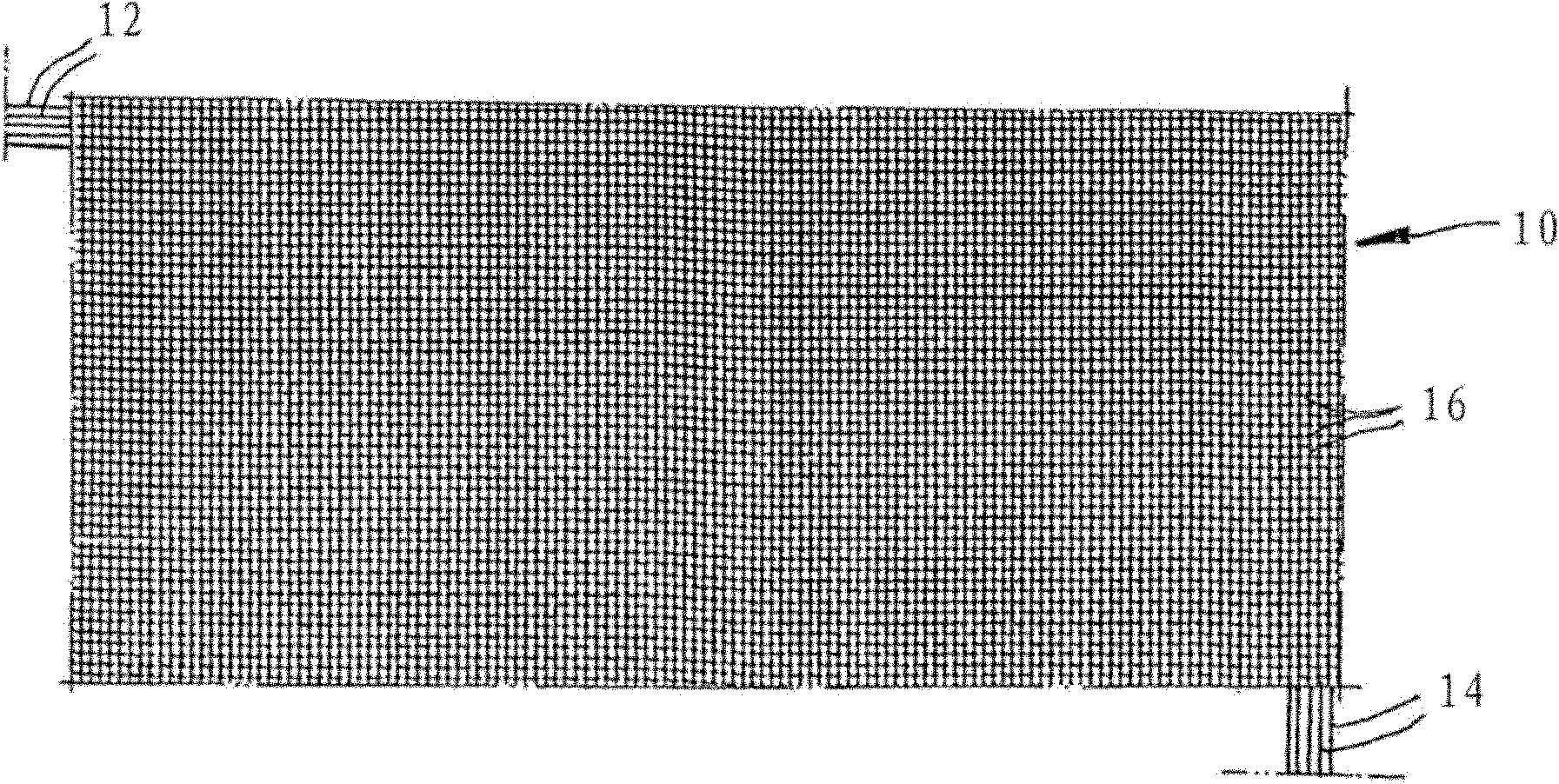
[0022] figure 1 A fabric web 10 is shown, which is woven in a mesh-like manner from interwoven PU threads 12 , 14 , wherein the mesh of threads delimits a gap 16 , for example in the shape of a quadrilateral. The gaps form approximately 40% of the total area as an open area.

[0023] The threads 12 , 14 are plastic fibers of a monofilament synthetic fabric, one surface of which is vapor-deposited on one side with a metallization (here aluminum with a layer thickness of approximately 80 nm).

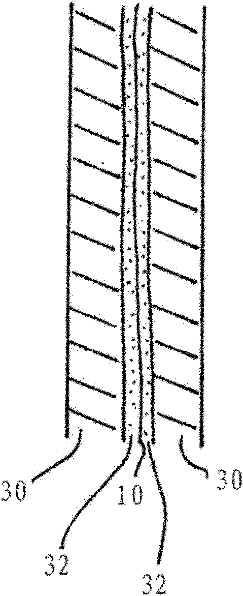
[0024] figure 2 In longitudinal section it is shown figure 1 How the fabric web 10 is introduced between a pair of glass plates 30 (typically each having a thickness of about 7 mm) in a double laminate type, wherein the fabric web 10 is introduced separately between each glass plate 30 and the fabric web 10 located in the middle A film 32 made of polyvinyl butyral (PVB) is provided. This device is processed by autoclaving in a vacuum (to avoid unfavorable gas bubbles) in such a way t...


PUM

PropertyMeasurementUnit
thicknessaaaaaaaaaa
thicknessaaaaaaaaaa
thicknessaaaaaaaaaa

Abstract

The invention relates to a surface portion made of crossing threads (12, 14) made from plastic filaments, said portion equipped as a woven fabric web (10) with two opposite surfaces and cutouts (16) formed therein. The invention provides that the fabric web has a metallization applied on one side thereof as the surface layer, and that between 15 and 80%, particularly between 20 and 70% of the fabric web is configured as an open surface in the form of net intermediate spaces.

Description

technical field [0001] The invention relates to a face part made of interwoven threads made of plastic fibers as a woven fabric web according to the preamble of claim 1 . Background technique [0002] Such devices are generally known in the prior art and are disclosed, for example, in the form of DE 10 2004 060 105 A1 by the inventor as a self-adhesive printing substrate made of perforated film and paper. Such fabric webs are designed to be white on the front side and black on the reverse side; the application of prints etc. takes place on the white side. If this printed substrate is mounted on a window pane or a corresponding transparent surface-carrying element, the print is visible from the outside as planar, but the observer from the inside cannot see through the black surface; The printed pattern on the side is not visible. Such methods allow a particularly advantageous construction of a larger advertising surface, which on the one hand is transparent from the inside ...

Claims


Application Information

Patent Timeline
Patent Type & Authority Applications(China)
IPC IPC(8): B32B15/14B32B15/20B32B17/06D03D9/00D06B11/00D06M11/83B32B17/00
CPCB32B27/02H01L31/02021B32B17/10247B32B27/30D06P5/00B32B17/10761B32B27/28D06P5/12D06M11/83B32B27/36B32B27/08B32B27/12D03D1/007D03D9/00B32B17/10036B32B27/06B32B27/40B32B5/024B32B27/306B32B2255/02B32B2255/205B32B2262/0276B32B2262/0292B32B2307/404B32B2307/412B32B2307/712B32B2307/75B32B2451/00B32B2590/00Y10T428/24802Y10T428/12535Y10T442/3382D10B2331/10D10B2401/16D10B2505/20D03D1/0076B32B2250/40B32B2307/402B32B2307/406B32B5/028B32B2307/732B32B2250/05D03D15/283B32B15/14D06B11/00
Inventor 鲁文.塞德勒彼得.查布雷塞克
Owner SEFAR
Learn More