Electrode assembly

Active Publication Date: 2017-09-21
SUUNTO OY
View PDF8 Cites 3 Cited by
  • Summary
  • Abstract
  • Description
  • Claims
  • Application Information

AI Technical Summary

Benefits of technology

[0017]Still yet, it is a further object of the present invention to provide a linking member which has at least two portions which form base portions for snaps and which have a higher degree of rigidity compared to a non-stretchable material portion connecting said at least two base portions. The linking member of the present inve

Problems solved by technology

Due to the existing technology and methods for detachably connecting telemetric transmitters it has not been realistic to incorporate heart rate monitor electrodes in to typical garments.
In fact, the primary road block to such incorporation has been the size and bulkiness of the standard garment snaps.
No clothing manufacture, nor consumer, has wanted 4 mm protrusions from their garments such as tops, shirts and sports bras.
As such, it would not be economical to wholly redesign the male portions of telemetric transmitters and the method in which they connect to an object having the necessary electrodes for measuring a user's heart rate.
However, several critical issues arise when attempting to merely minimize the existing standardized snap.
The main issue is the integrity of the connection between the male stud and the snap.
Any amount over movement of the male stud with

Method used


Image

  • Electrode assembly
  • Electrode assembly
  • Electrode assembly

Examples


Example

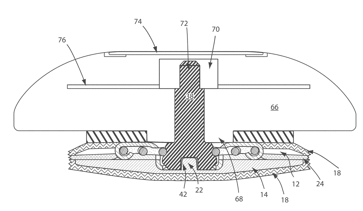
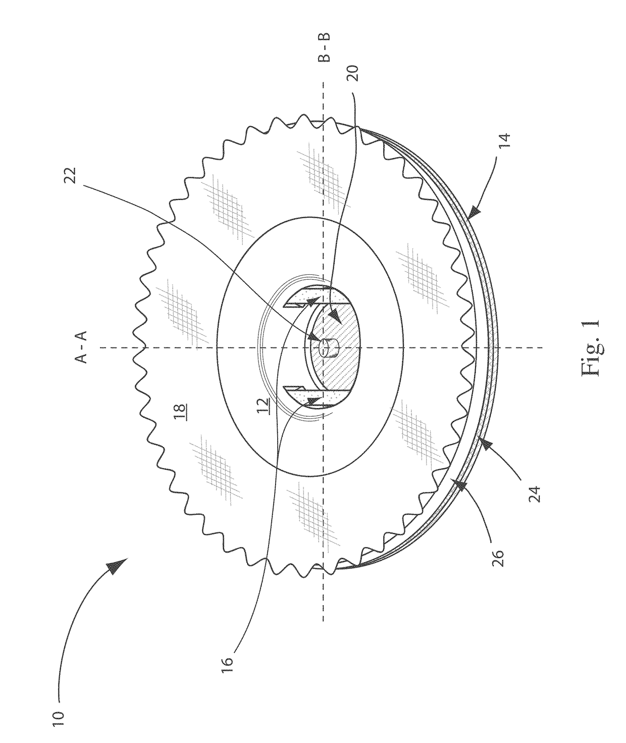
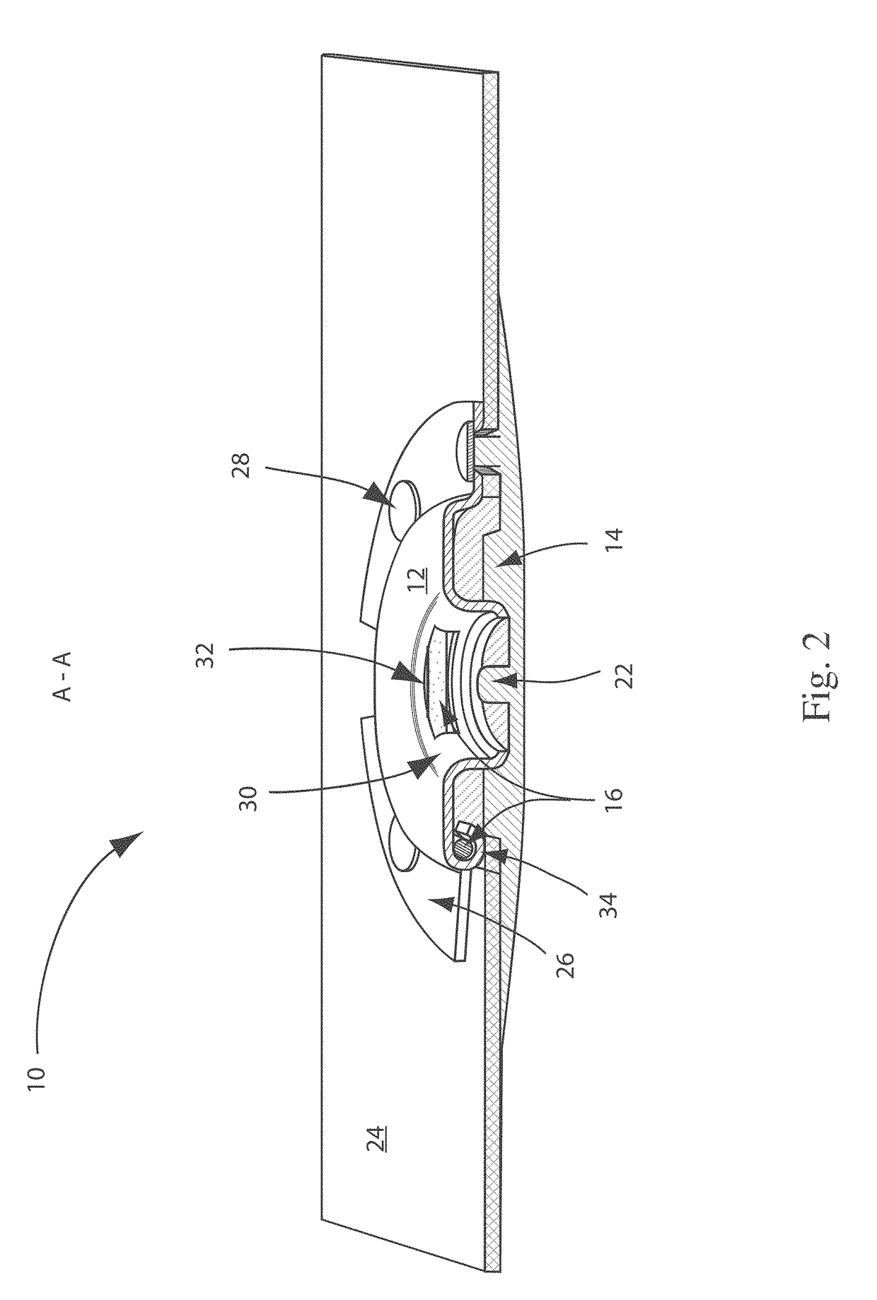
[0031]A snap 10 in accordance with an embodiment of the present invention is shown in FIG. 1. The snap is shown integrated within a material 18. As can be seen from the figure, the upper cap portion 12 of the snap 10 is essentially flush with the material 18, i.e. there is no significant protrusion. Such an integrated snap design is highly desirable when transitioning from stand alone heart rate monitor belts worn in addition to regular clothing to integrating the functionality of a heart rate monitor in to clothing itself

[0032]As discussed herein, a heart rate monitor belt is the combination of electrodes and snaps in such an arrangement that they can be used to determine, measure and / or monitor the heart beat of an individual or animal wearing the belt. A heart rate monitor belt may be a standalone article in the form of, for example, a belt having a plurality of electrodes connected to a pair of snaps which can be worn, for example around the torso of a user. Additionally, a hear...


PUM


Abstract

The present invention relates generally to an electronic device having a housing and at least one male connection portion for detachably connection the electronic device to a female snap. The male connection portion comprises a stud having a male head portion capable of fitting within a socket region of a snap. The male head portion has a terminal end which is the terminal end of the stud and a second end which separates the male head portion from a mid-portion, and an end portion opposite the male head portion. The end portion has a terminal end which is second terminal end of the stud. A mid-portion is between the male head portion and the end portion. The stud is in electrical contact with an electronic component of the electronic device, and the head portion has a centered cavity open at the terminal end of the male head portion.

Description

FIELD OF INVENTION[0001]The present invention relates generally to an electrode assembly having at least two snap portions. More particularly, embodiments of the present electrode assembly are particularly well suited for receiving, holding and enabling an electrical connection with male ends of a telemetric device. Examples of the present electrode assemblies are integrated within a heart rate monitor belt or garment.BACKGROUND OF THE INVENTION[0002]Currently, there are heart rate monitor belts which people can wear underneath their clothing in order to monitor their heart rate. Such belts are typically designed such that a telemetric transmitter is detachably connected to a belt having two electrodes which are in contact with the user's skin in the chest region of the user's torso. The electrodes identify an electric ECG pulse caused by the heart and then the detachable telemetric transmitter transmits data indicative of the user's heart beat with the use of wireless magnetic near...

Claims


Application Information

Patent Timeline
IPC IPC(8): A61B5/0416A61B5/00A61B5/274
CPCA61B5/0416A61B2562/0209A61B5/6804A61B5/0006A61B5/6831A61B5/274A61B5/282
Inventor PERNU, KIMMOSELBY, TAPIOLEHTINEN, OSSI
Owner SUUNTO OY
Why Eureka
Try Eureka