
Method of Monitoring Operation of An Electric Power System and Monitoring System

a monitoring system and electric power technology, applied in the direction of electric devices, instruments, transportation and packaging, etc., can solve the problems of low number of attacks and vulnerabilities known for control and automation systems and their special protocols, inability to detect new or unknown attacks, and limited usefulness of blacklist approaches

Active Publication Date: 2014-02-27
OMICRON ELECTRONICS GMBH
View PDF5 Cites 31 Cited by
  • Summary
  • Abstract
  • Description
  • Claims
  • Application Information

AI Technical Summary

Benefits of technology

The patent describes a system model that defines a set of constraints for a power utility automation system. These constraints are based on the configuration information and application knowledge. The system model helps to efficiently verify whether the monitored data messages correspond to valid behavior. The process for automatically creating the system model starts by determining the internal data model of the devices in the system using SCL files or other configuration data files. This information helps to identify the device type, vendor information, and its capabilities. It also identifies which devices will communicate with each other and which messages are expected at certain locations in the system. This information helps to generate access control lists for the device's data model. Overall, the system model improves the reliability and security of the power utility automation system.

Problems solved by technology

The need to transmit power over longer distances, to perform voltage conversion in a transformer substation or to distribute power requires complex electric systems.
Examples for such critical events include security intrusions, operator errors, timing issues, hardware faults or any critical or incorrect state of the electric power system and / or its power utility automation system.
While the blacklist approach may be used to detect critical events in power utility automation systems, there may be problems associated with such an approach.
New or unknown attacks cannot be detected.
In the context of electric power systems, the number of attacks and vulnerabilities known for control and automation systems and their special protocols is very low.
The usefulness of blacklist approaches is thus especially limited for IDS in electric power systems.

Method used


Image

  • Method of Monitoring Operation of An Electric Power System and Monitoring System
  • Method of Monitoring Operation of An Electric Power System and Monitoring System
  • Method of Monitoring Operation of An Electric Power System and Monitoring System

Examples


Embodiment Construction

[0072]Embodiments of the invention will be described in more detail with reference to the drawings. While some of the embodiments will be described in specific contexts, such as substations of an electric power system which are transformers or power plants, the methods and monitoring systems are not limited to these contexts. Embodiments may be utilized in particular for monitoring operation, and in particular for detecting intrusions, in substations of electric power systems which have a power utility automation system in the form of a substation automation system.

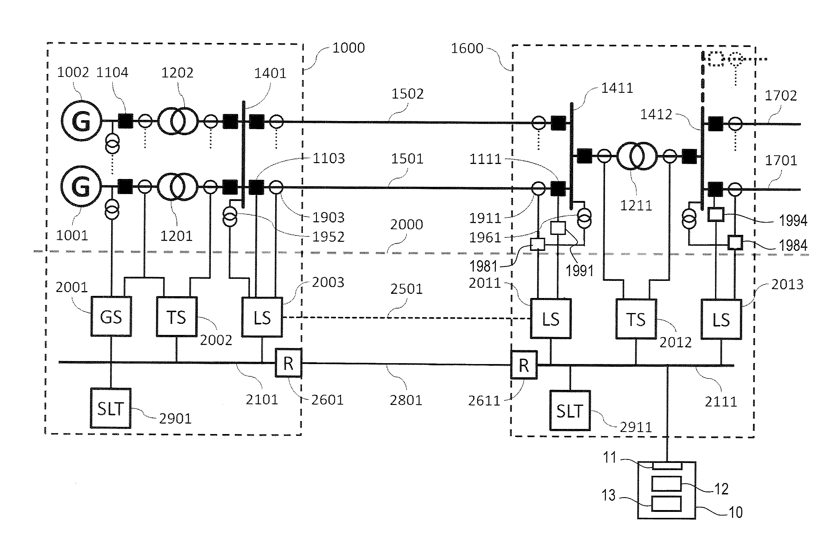
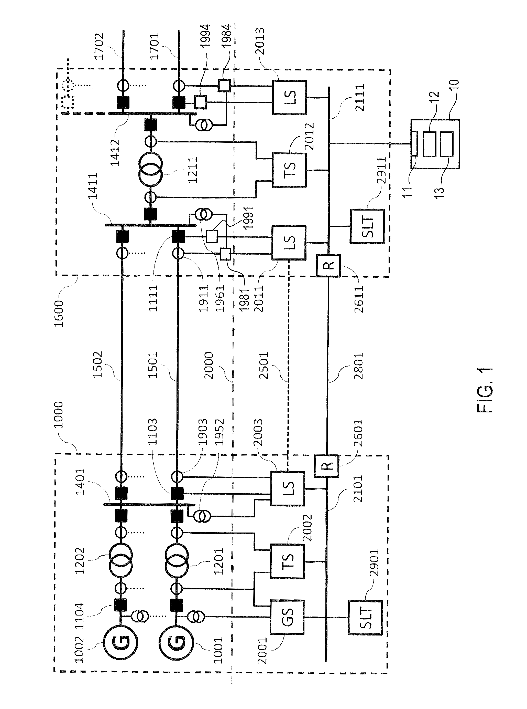
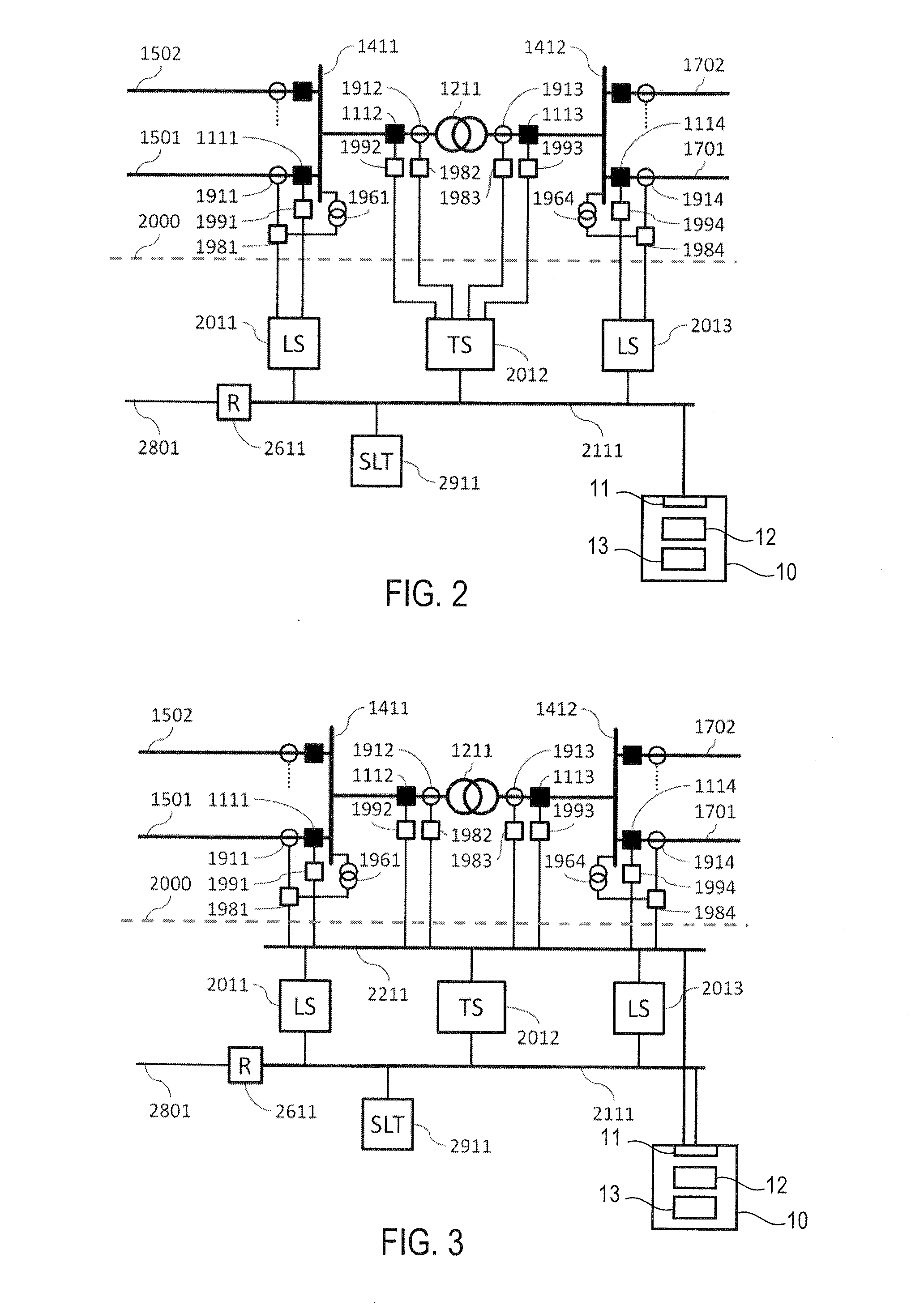
[0073]FIG. 1 to FIG. 3 show in diagrammatic and highly simplified form fundamental components of an electric power system in which a monitoring system 10 of an embodiment may be used.

[0074]Generally, and as will be explained in more detail below, a monitoring system 10 of an embodiment comprises an interface 11 for communication with a communication network of a power utility automation system. Using the interface, data m...


PUM


Abstract

In a method, operation of an electric power system which has a power utility automation system (1981-1984, 1991-1994) is monitored. The power utility automation system (1981-1984, 1991-1994) comprises a plurality of intelligent electronic devices (IEDs) (1981-1984, 1991-1994) communicating via a communication network. During operation of the electric power system, properties of the electric power system are monitored, the monitored properties comprising monitored data messages which are transmitted by the plurality of IEDs (1981-1984, 1991-1994) over the communication network. The monitored data messages are evaluated based on configuration information for the power utility automation system (1981-1984, 1991-1994) to detect a critical event. An alert signal is generated in response to detection of the critical event.

Description

FIELD OF THE INVENTION[0001]The invention relates to a method and a monitoring system for monitoring operation of an electric power system. The invention relates in particular to such a method and monitoring system which is configured to perform substation automation monitoring to detect a critical event, such as a security intrusion, during operation of the electric power system.BACKGROUND OF THE INVENTION[0002]Electric power systems for high and medium voltages are widely used. The need to transmit power over longer distances, to perform voltage conversion in a transformer substation or to distribute power requires complex electric systems. In recent years, so-called automation systems have become increasingly popular which increase the degree of automation attained in an electric power system. For illustration, substations for power distribution in high and medium voltage power networks include primary or field devices such as electrical cables, lines, bus bars, switches, breaker...

Claims


Application Information

Patent Timeline
Patent Type & Authority Applications(United States)
IPC IPC(8): G01R21/133
CPCG01R21/133H04L43/12H04L41/0631H04L43/00H04L63/14Y04S40/00Y04S40/20
Inventor KLIEN, ANDREASMARINESCU, CRISTIAN
Owner OMICRON ELECTRONICS GMBH
Learn More