Low radar cross section array panel

a technology of array panels and radars, applied in the direction of antennas, show hangers, show stands, etc., can solve the problems of large rcs, unsatisfactory radar reflection, and large rcs, and achieve the effect of reducing the rcs for the overall array, reducing assembly weight, and easy assembly adjustment design

Active Publication Date: 2014-03-06
BAE SYST INFORMATION & ELECTRONICS SYST INTERGRATION INC
View PDF2 Cites 2 Cited by
  • Summary
  • Abstract
  • Description
  • Claims
  • Application Information

AI Technical Summary

Benefits of technology

[0007]More particularly, the low RCS array support panel in one embodiment, offers support for elements that do not require a ground plane, while reducing the RCS for the overall array, and at the same time providing a lower assembly weight. The low RCS array support panel permits the formation of antenna arrays of varying sizes with minimal reflecting surfaces. The low RCS array support panel in one embodiment provides support for antenna elements by using an easily assembled adjustable design. The array support panel also implements convenient pre-formed methods of construction so that antenna arrays may be fabricated and supported with a low RCS grid or lattice.

Problems solved by technology

Typical array panels provide a ground plane that forms a large reflecting surface, causing undesirable radar reflection and a large Radar Cross Section (RCS).
Particularly in the battlefield, a large RCS is a large detriment and can be extremely dangerous.

Method used


Image

  • Low radar cross section array panel
  • Low radar cross section array panel
  • Low radar cross section array panel

Examples


Embodiment Construction

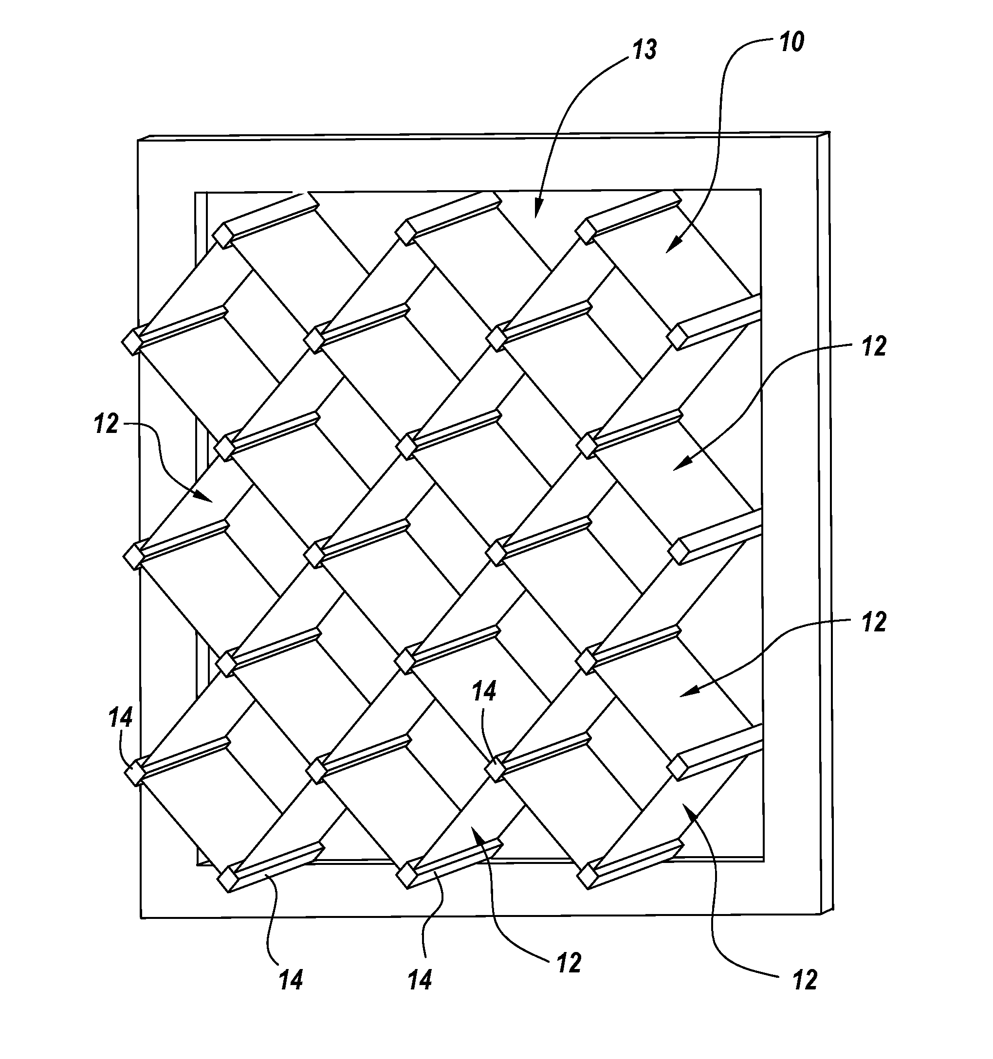
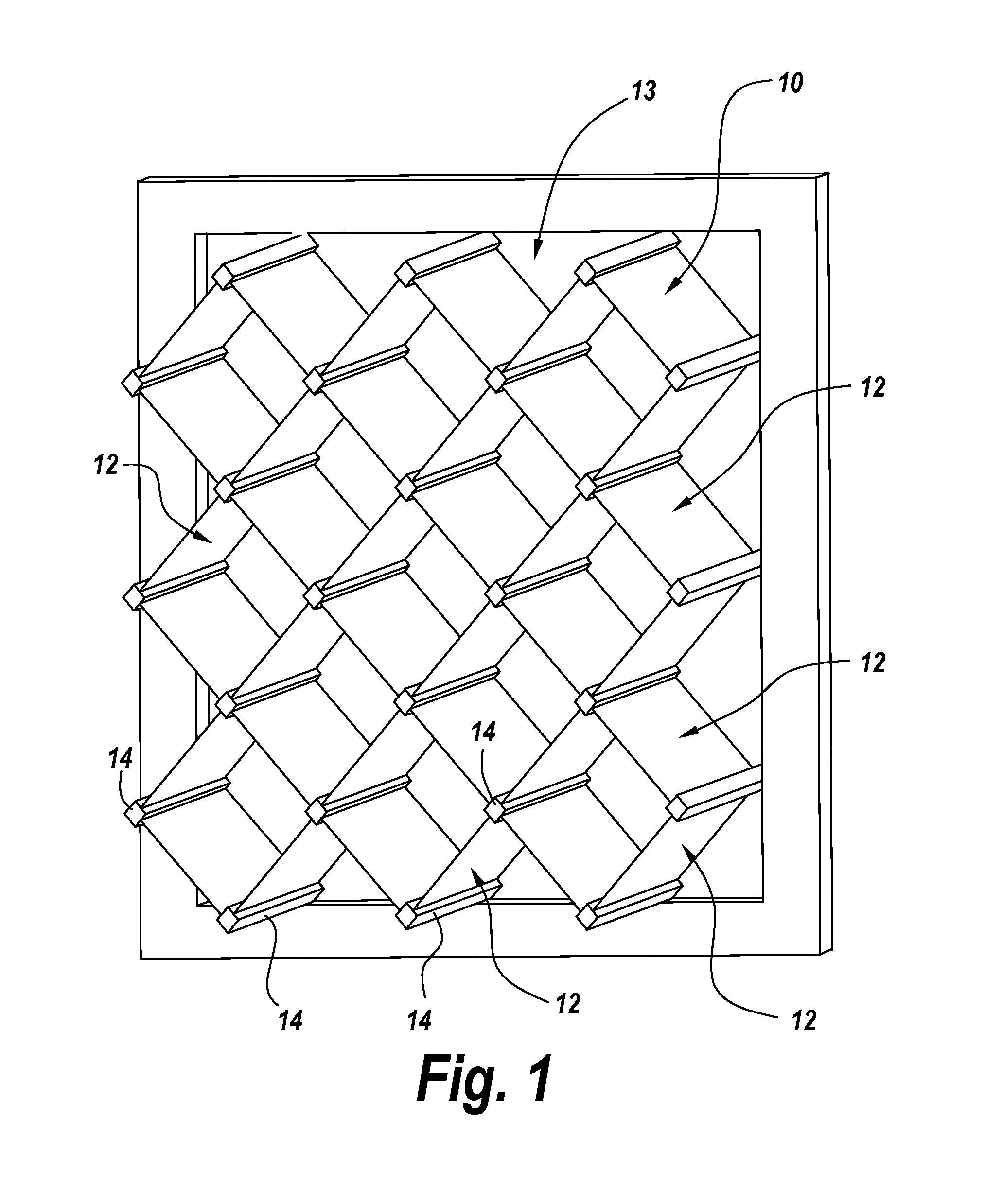
[0015]Referring now to FIG. 1, a planar antenna array 10 is composed a number of printed circuit card antenna elements 12 located in a diamond shaped pattern across an antenna array support panel 13, with antenna element printed circuit cards 12 being mounted between notched support columns 14 as illustrated.

[0016]One of the problems with the mounting of such an antenna array is to provide a support structure that has a relatively low radar cross section.

[0017]If, for instance the elements are mounted to a metalized support panel, for instance to provide a ground plane or the like for the antenna array, then the panel itself presents a relatively high radar cross section which is undesirable.

[0018]There is therefore a requirement to provide a suitable mounting system for antenna arrays, whether of the printed circuit card variety shown in FIG. 1 or individual elements extended up from a ground plane. It is the purpose of array support panel 13 to support the antenna array elements i...


PUM

PropertyMeasurementUnit
frequencyaaaaaaaaaa
radar reflectivityaaaaaaaaaa
latticeaaaaaaaaaa

Abstract

A low RCS array panel employs a number of linkable support segments. Each support segment has several junctions spaced along it, and the support segments are designed to connect with each other at the junctions to create a support grid. The segments can connect orthogonally, and the junctions can be spaced according to the frequency performance requirements for the antenna the array panel is designed to support.

Description

RELATED APPLICATIONS[0001]This Application claims rights under 35 USC §119 (e) from U.S. Provisional Application Ser. No. 61 / 522,754 filed Aug. 12, 2011, the contents of which are incorporate herein by reference.STATEMENT OF GOVERNMENT INTEREST[0002]The invention was made with United States Government assistance under contract No. FA86290-06-G-4028-0008 awarded by the US Air Force. The United States Government has certain rights in the invention.FIELD OF THE INVENTION[0003]The present invention relates to antenna support panels, and more particularly to low weight and low reflective antenna array support panels.BACKGROUND OF THE INVENTION[0004]When supporting antenna elements in an array, element size and frequency range dictate the weight for the antenna array support. Typical array panels provide a ground plane that forms a large reflecting surface, causing undesirable radar reflection and a large Radar Cross Section (RCS). Planar array supports offer support for the element weigh...

Claims


Application Information

Patent Timeline
Patent Type & Authority Applications(United States)
IPC IPC(8): H01Q1/12
CPCH01Q1/12H01Q21/061Y10T29/49016H01Q1/14
Inventor THOMPSON, JR., BASIL W.SMITH, ROBERT D.GARNETT, ALMER M.
Owner BAE SYST INFORMATION & ELECTRONICS SYST INTERGRATION INC
Why Eureka
Try Eureka