Conduction breaking device

Inactive Publication Date: 2014-03-06
TOYODA GOSEI CO LTD
View PDF7 Cites 50 Cited by
  • Summary
  • Abstract
  • Description
  • Claims
  • Application Information

AI Technical Summary

Benefits of technology

[0008]Accordingly, it is an object of the present invention to provide a conduction breaking device capable of e

Problems solved by technology

When the conduction breaking device is operated to break the conductive body in a current-carrying state, an arc may occur due to the potential diff

Method used


Image

  • Conduction breaking device
  • Conduction breaking device
  • Conduction breaking device

Examples


first embodiment

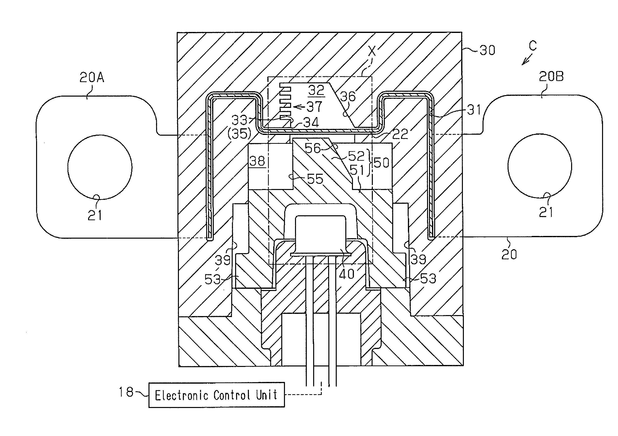
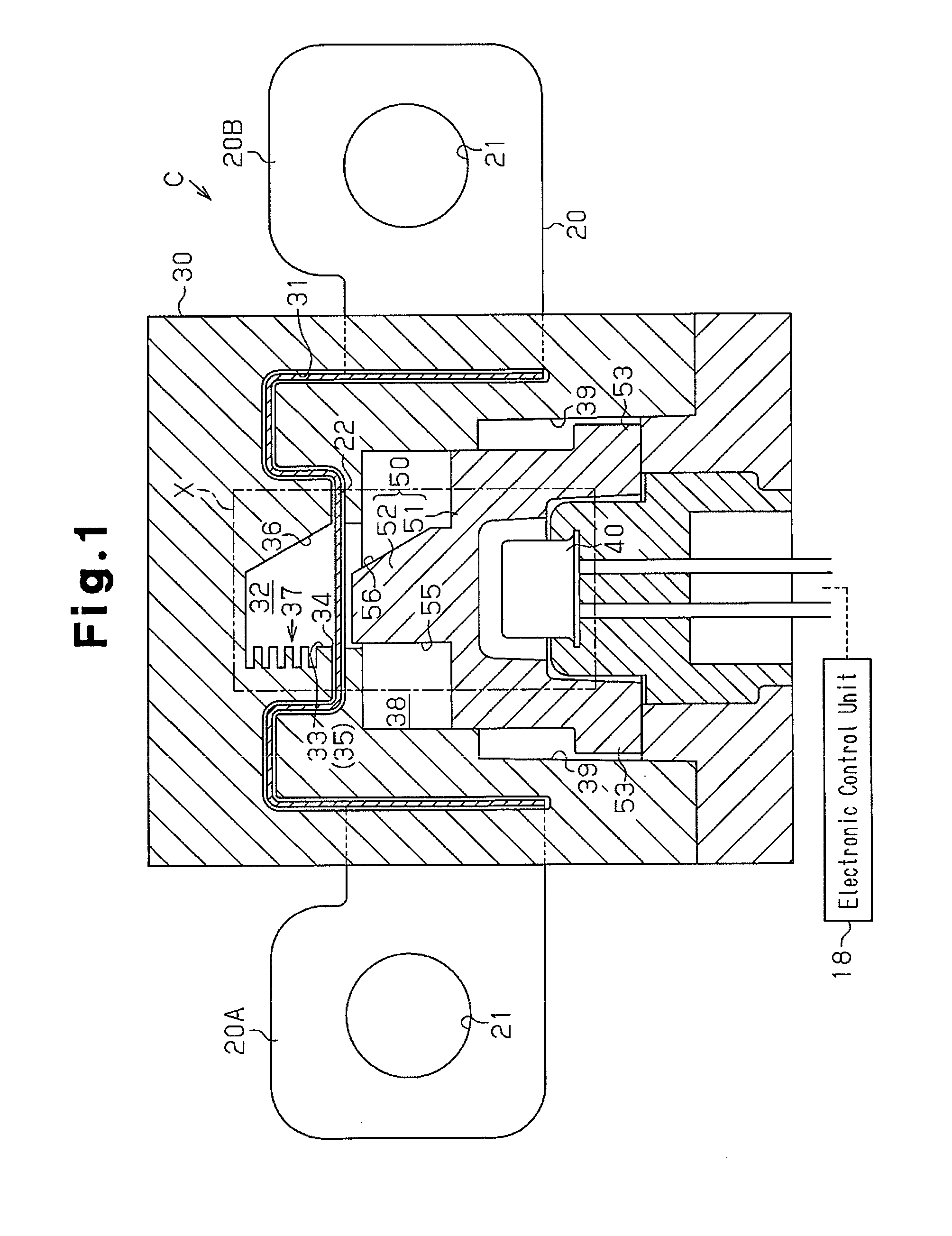
[0023]A conduction breaking device C according to a first embodiment of the present invention will be described below with reference to FIGS. 1 to 4.

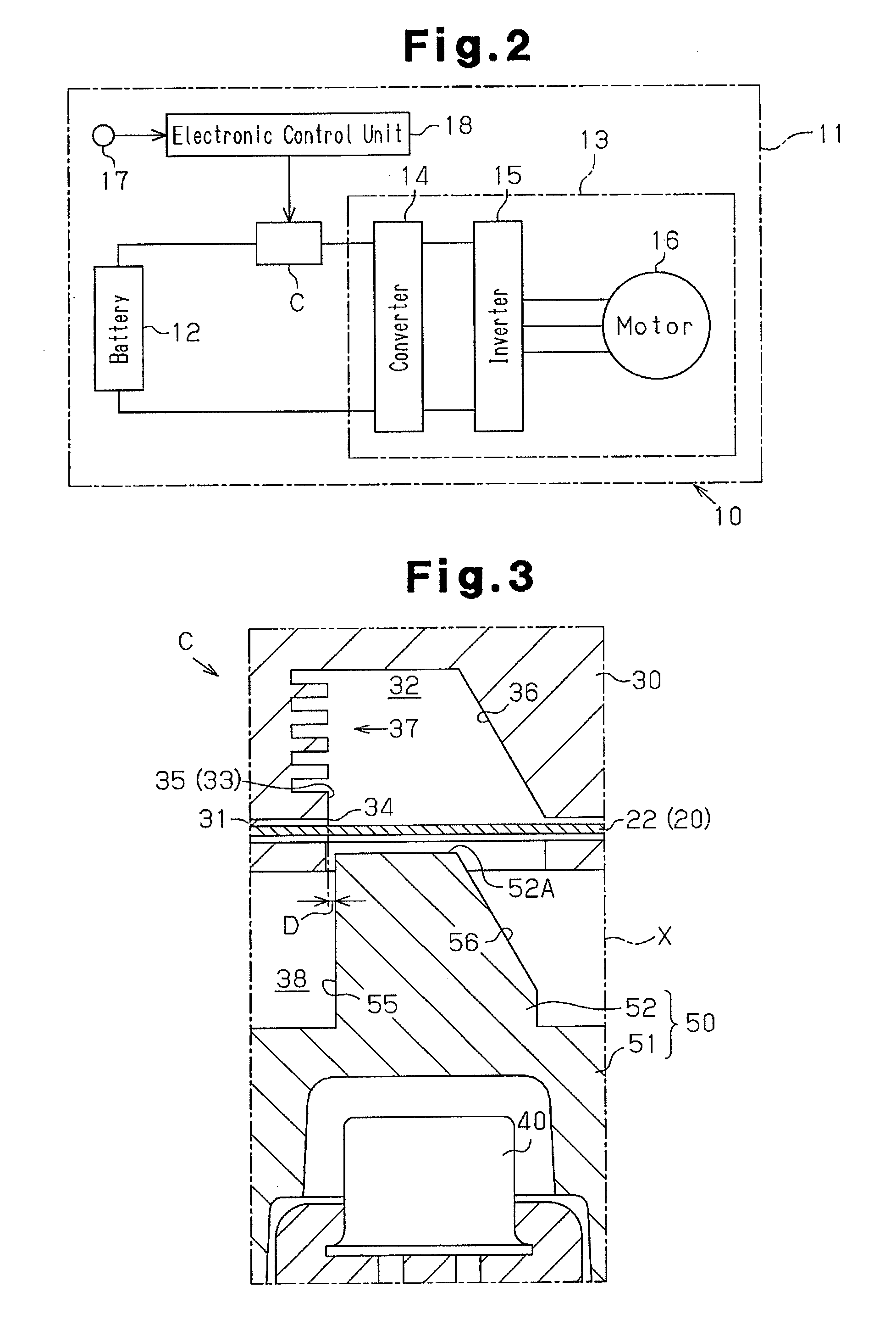
[0024]FIG. 2 illustrates an electric circuit 11 to which the conduction breaking device C according to the first embodiment is applied. The electric circuit 11 includes a pair of devices, which are a storage battery 12 and an electric device 13. In the electric circuit 11, the electric device 13 is operated by DC electricity supplied from the storage battery 12. The electric device 13 is configured by a converter 14, which increases the voltage of electricity input from the storage battery 12 and outputs the increased voltage, an inverter 15, which converts DC electricity input from the converter 14 into AC electricity suitable for driving a motor and outputs the AC electricity, and a motor 16, which is driven by the AC electricity output from the inverter 15.

[0025]The electric circuit 11 is mounted on a vehicle 10. When the vehicle 10 ...

second embodiment

[0061]A conduction breaking device C according to a second embodiment of the present invention will be described below with reference to FIG. 5 and FIG. 6.

[0062]The second embodiment is different from the first embodiment in the structure for extinguishing an arc occurring between the cut ends 23 and 24 inside the arc-extinguishing chamber 32.

[0063]According to the second embodiment, the entire inner walls of the arc-extinguishing chamber 32 and the entire cutting member 50 are made of a material having a thermal conductivity of 0.5 W / (m·K) or more. Thus, for the inner walls of the arc-extinguishing chamber 32 and the cutting member 50, the area that at least contains a position that the cut end 24 of the first cut piece approaches and a position that the cut end 23 of the second cut piece approaches at the cutting of the conductive body 20 is made of the above material. A general-purpose plastic material mixed with a filler may be used for the above material. The uneven portion 37 ...

third embodiment

[0070]A conduction breaking device C according to a third embodiment of the present invention will be described below with reference to FIG. 7.

[0071]The third embodiment is different from the first and second embodiments in the structure for extinguishing an arc between the cut ends 23 and 24 in the arc-extinguishing chamber 32.

[0072]According to the third embodiment, the entire inner walls of the arc-extinguishing chamber 32 and the entire cutting member 50 are made of a plastic material that generates ablation gas due to an arc occurring between the cut ends 23 and 24. Thus, for the cutting member 50 (the blade 52), an area A1 between a position that the cut end 23 of the second cut piece approaches and a position that the cut end 24 of the first cut piece approaches at the cutting of the breakable portion 22 is made of the above plastic material. For the arc-extinguishing chamber 32, an area A2 between a position that the cut end 23 of the second cut piece approaches and a positi...


PUM


Abstract

A conduction breaking device includes a conductive body arranged between a pair of devices in an electric circuit, a gas generator, which is arranged away from the conductive body and generates gas, and a cutting member, which is arranged between the conductive body and the gas generator. The cutting member is moved due to gas from the gas generator to cut the conductive body, divides the conductive body into a first cut piece and a second cut piece, which have cut ends separated from each other, and breaks the conduction between the devices. The conduction breaking device includes an arc-extinguishing chamber. In the arc-extinguishing chamber, the conductive body is cut by the cutting member and an arc occurring between the cut end of the first cut piece and the cut end of the second cut piece is extinguished.

Description

BACKGROUND OF THE INVENTION[0001]The present invention relates to a conduction breaking device for breaking conduction between a pair of devices in an electric circuit by cutting a conductive body extending between the devices.[0002]Electric circuits are provided with a conduction breaking device for breaking conduction between devices by being operated when malfunction occurs in a device in the electric circuit or a system on which the electric circuit is mounted. As one form thereof, a conduction breaking device has been proposed that forcibly cuts a conductive body located between devices by moving a blade (cutting member) with gas (see Japanese Laid-Open Patent Publication No. 11-232979, for example).[0003]The conduction breaking device of the above type includes a case for housing part of the conductive body. A gas generator for generating gas is arranged away from the conductive body inside the case. An accommodating chamber is formed between the conductive body and the gas ge...

Claims


Application Information

Patent Timeline
IPC IPC(8): H01H33/06H01H33/74H01H33/18
CPCH01H33/06H01H33/74H01H33/182H01H9/443H01H39/006
Inventor NAKAMURA, YOSHIKIFUKUYAMA, TAKAKIKAMEDA, YOSHIAKI
Owner TOYODA GOSEI CO LTD
Why Eureka
Try Eureka