Aircraft throttle control device including a cam coupling

a technology of throttle control and cam coupling, which is applied in the direction of control initiation means, aircraft power plants, and personal actuation, etc., can solve the problems of large space occupation of the coupling system and heavy weigh

Active Publication Date: 2014-03-06
SAFRAN ELECTRONICS & DEFENSE
View PDF5 Cites 5 Cited by
  • Summary
  • Abstract
  • Description
  • Claims
  • Application Information

AI Technical Summary

Benefits of technology

[0011]To this end, the invention provides an aeroengine control device comprising a mount, having pivotally mounted thereon a code wheel together with a main lever, and a secondary lever, both for turning the code wheel, each lever being movable between a rest position and a maximum actuation position, the secondary lever being mounted to pivot on the main lever. A first cam path is formed on a part secured to the code wheel and a second cam path is formed on the mount, the two cam paths having respective facing portions in which there is received a finger that is mounted on the main lever to slide parallel to the code wheel, with a connecting rod permanently connecting the finger to the secondary lever. The cam paths are arranged in such a manner that the main lever can move the code wheel when the main lever is moved while the secondary lever is in its rest position, and the secondary lever can move the code wheel when the secondary lever is moved while the main lever is in its rest position, with movement of either lever being prevented when the other lever is away from its rest position.
[0012]Thus, action on the main lever causes the finger to move along a circular arc, thereby directly driving the code wheel, and action on the secondary lever causes the finger to move in a straight line, which movement is transformed by the first cam path into turning of the code wheel. The finger co-operates with the cam paths that are arranged in such a manner that the main lever can drive the code wheel when the main lever is moved while the secondary lever is in the rest position, and the secondary lever can drive the code wheel when the secondary lever is moved while the main lever is in the rest position, with movement of either lever being prevented when the other lever is away from its rest position.
[0015]It is thus possible to move one of the levers while the other lever is close to its rest position, with the other lever then being returned automatically to its rest position.
[0020]This makes it possible to limit transmission of force from the code wheel to the secondary lever while the code wheel is being moved by the main lever.

Problems solved by technology

The coupling system occupies a considerable amount of space and is heavy, in particular because of the intermediate wheel.

Method used


Image

  • Aircraft throttle control device including a cam coupling
  • Aircraft throttle control device including a cam coupling
  • Aircraft throttle control device including a cam coupling

Examples


Embodiment Construction

[0032]The throttle control device described herein is arranged to control both the fuel flow rate and a thrust reversal device of an aeroengine.

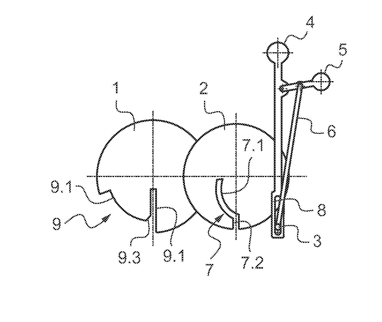
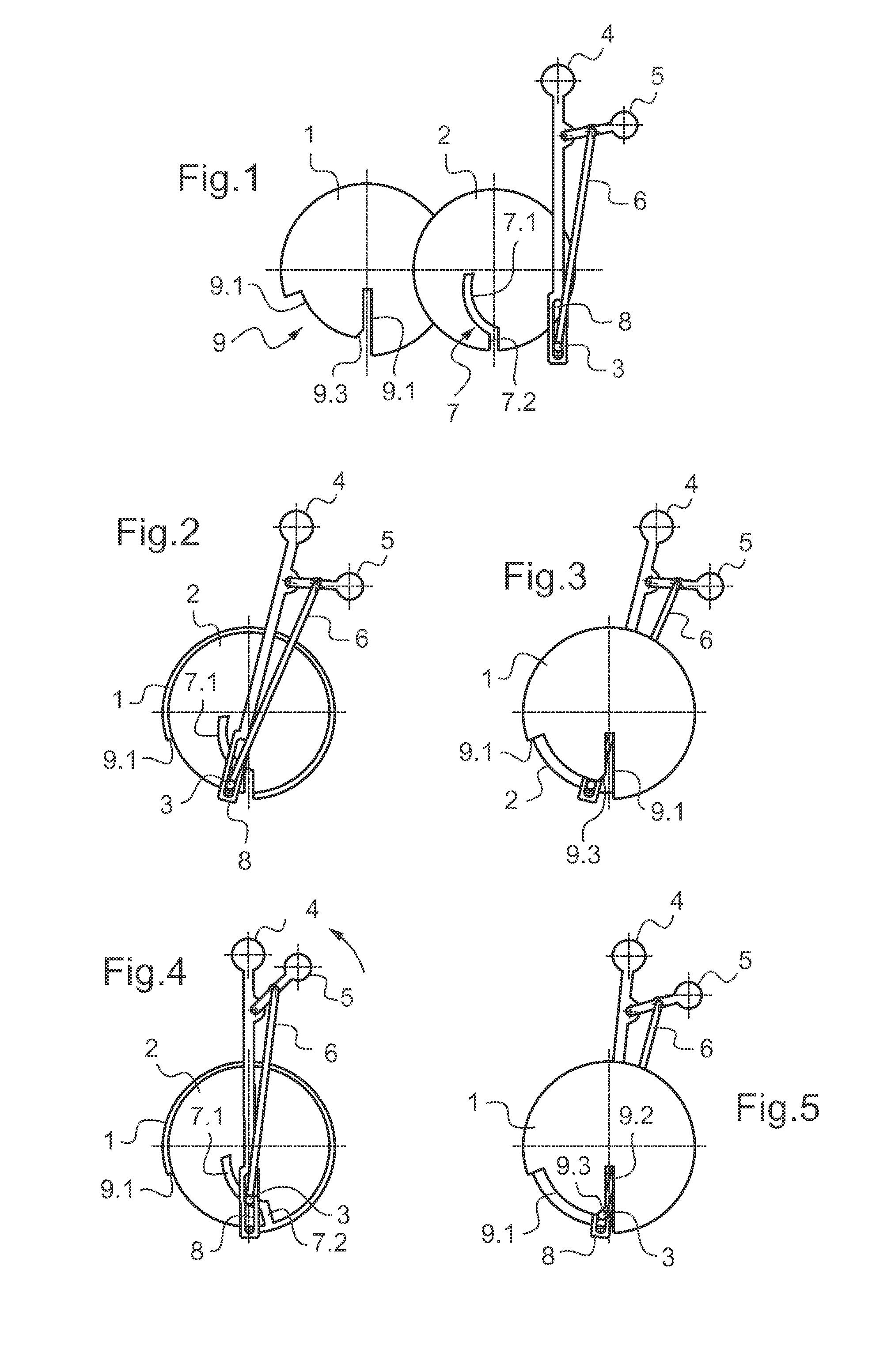
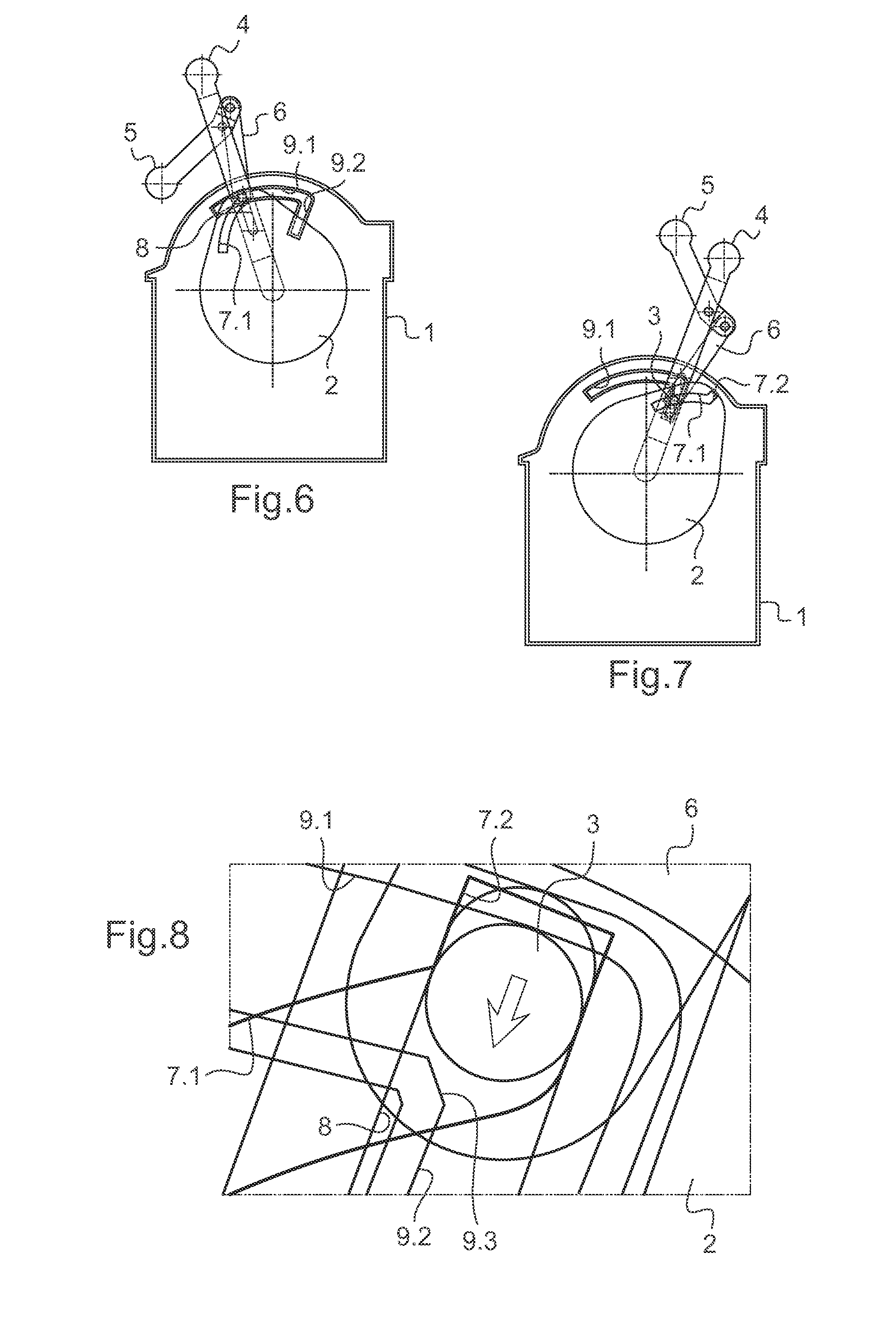
[0033]With reference to FIGS. 1 to 5, the control device comprises a mount 1 having a code wheel 2 pivotally mounted thereon. Sensors for sensing the angular position of the code wheel 2 (not shown in the figure) are mounted on the mount 1 in register with the outline of the code wheel 2.

[0034]A main lever 4 is mounted on the mount 1 to pivot about the same axis as the code wheel 2. The main lever 4 has a radially offset structure with a secondary lever 5 mounted thereon to pivot about an axis parallel to the axis of rotation of the code wheel 2 and of the main lever 4. Each of the levers 4 and 5 pivots between a rest position (shown in FIG. 1 for both levers) and a maximum actuation position. The main lever 4 is a throttle control lever for controlling fuel flow rate, and its maximum actuation position can be seen on the right of FIG. 1: th...


PUM


Abstract

An aeroengine control device including a mount and having pivotally mounted thereon a code wheel together with a main lever and a secondary lever, both for turning the code wheel. Each lever is movable between a rest position and a maximum actuation position. The secondary lever is mounted to pivot on the main lever. Cam paths are mounted on the code wheel and on the mount in such a manner that the main lever can move the code wheel when the main lever is moved while the secondary lever is in the rest position. The secondary lever can move the code wheel when the secondary lever is moved while the main lever is in the rest position, with movement of either lever being prevented when the other lever is clearly away from its rest position.

Description

CROSS-REFERENCE TO RELATED APPLICATIONS[0001]This application is a Continuation of co-pending application Ser. No. 13 / 500,824, filed on 6 Apr. 2012, which is a U.S. National Stage of International Application No. PCT / EP2010 / 006057 filed on Oct. 5, 2010, for which priority is claimed under 35 U.S.C. §120; and this application claims priority of application No. 09 / 04760 filed in France on Oct. 6, 2009 under 35 U.S.C. §119; the entire contents of all of which are hereby incorporated by reference.BACKGROUND OF THE INVENTION[0002]1. Field of the Invention[0003]The present invention relates to an aeroengine throttle control device.[0004]2. Brief Discussion of the Related Art[0005]Modern turbojets are fitted with a thrust reversal device that enables a fraction of the exhaust stream leaving the turbojet to be directed towards the front of the turbojet (generally in a direction that makes an angle of about 45° relative to the forward direction of the aircraft) in order to assist the slowing...

Claims


Application Information

Patent Timeline
Patent Type & Authority Applications(United States)
IPC IPC(8): B64D31/04
CPCB64D31/04
Inventor ELABELLAOUI, HAFIDBESOLD, JEAN-ERICPAUTARD, SEBASTIENCARTRY, THIERRYENGLER, DAVIDMERLET, ETIENNE
Owner SAFRAN ELECTRONICS & DEFENSE
Why Eureka
Try Eureka