Reactive Power Regulation

a technology of reactive power and control panel, applied in the direction of electric generator control, mechanical equipment, machines/engines, etc., can solve the problems of unstable control and inability to react quickly enough, and achieve the effect of quick response and quick response with local control

Active Publication Date: 2014-03-06
GE RENEWABLE TECH WIND BV
View PDF3 Cites 31 Cited by
  • Summary
  • Abstract
  • Description
  • Claims
  • Application Information

AI Technical Summary

Benefits of technology

[0012]In some embodiments, a local reactive power control system may switch from the central control mode to the local control mode when a measured local variable passes a local limit value for the wind turbine. An exceptional grid condition will generally be translated in an exceptional grid condition within the wind park. An aspect of these embodiments is that a local control system does not have to wait for a central control system to detect an abnormality and translate that abnormality into control signals. Instead a local control system is able to measure the abnormality and quickly respond. Optionally, the switch to a local control made is only made if the measured local variable passes a local limit value during at least a predetermined period of time. Preferably, the local limit values for each wind turbine are determined substantially such that in normal grid conditions, the wind park operates in the central control mode and that in or near exceptional grid conditions, the wind park operates in the local control mode. An aspect of these embodiments is that in normal grid conditions, the more stable centralised control may be used, whereas in or near exceptional grid conditions, a quicker response with the local control is available. According to these embodiments, in exceptional grid conditions, all wind turbines with local reactive power control systems may be in local control mode or only a part of them. A TSO may determine what “normal” grid conditions are. Any grid condition that is not considered “normal” may be considered “exceptional”. An example of an exceptional grid condition may be e.g. a grid voltage outside predefined boundary values.

Problems solved by technology

However a disadvantage of a centralised control may be that such a control is not always able to react sufficiently quickly to grid abnormalities.
An advantage of a decentralised control may be that it is quicker to react to grid abnormalities, but a disadvantage can be that the control can be unstable.

Method used


Image

  • Reactive Power Regulation
  • Reactive Power Regulation
  • Reactive Power Regulation

Examples


Embodiment Construction

[0039]Throughout the description reference is made to a maximum or minimum amount of reactive power, to a positive or negative amount of reactive power, as well as to an increase or decrease in reactive power. Within the scope of this description, a positive reactive power is considered capacitive reactive power; a maximum amount of reactive power is thus considered to be the so maximum possible capacitive reactive power, and an increase in reactive power is thus considered to be an increase in capacitive power (or a decrease in inductive power). A negative reactive power is considered to be inductive reactive power; a minimum amount of reactive power is thus considered to be the maximum possible inductive reactive power, and a decrease in reactive power is thus considered to be an increase in inductive power (or a decrease in capacitive power).

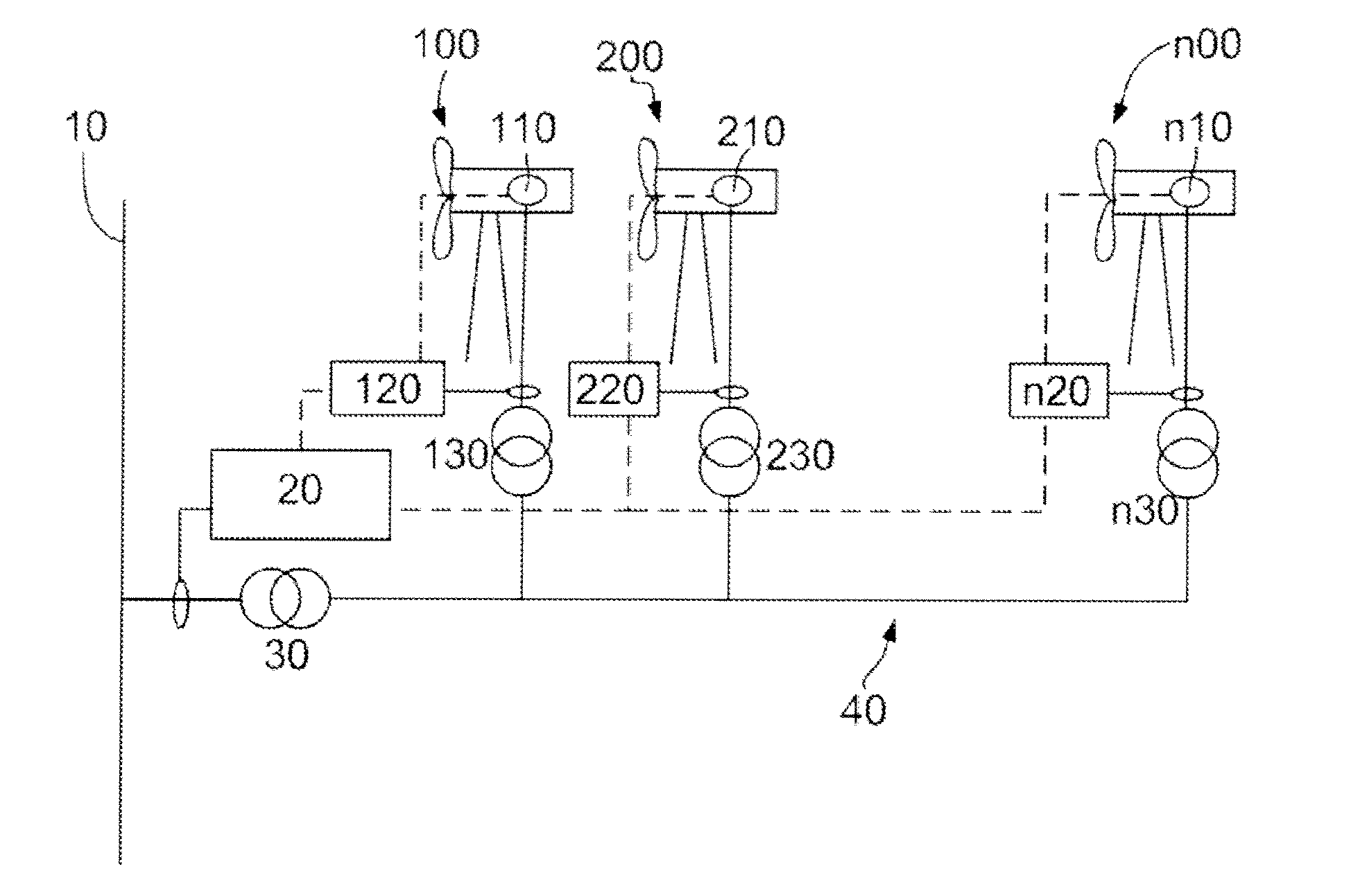
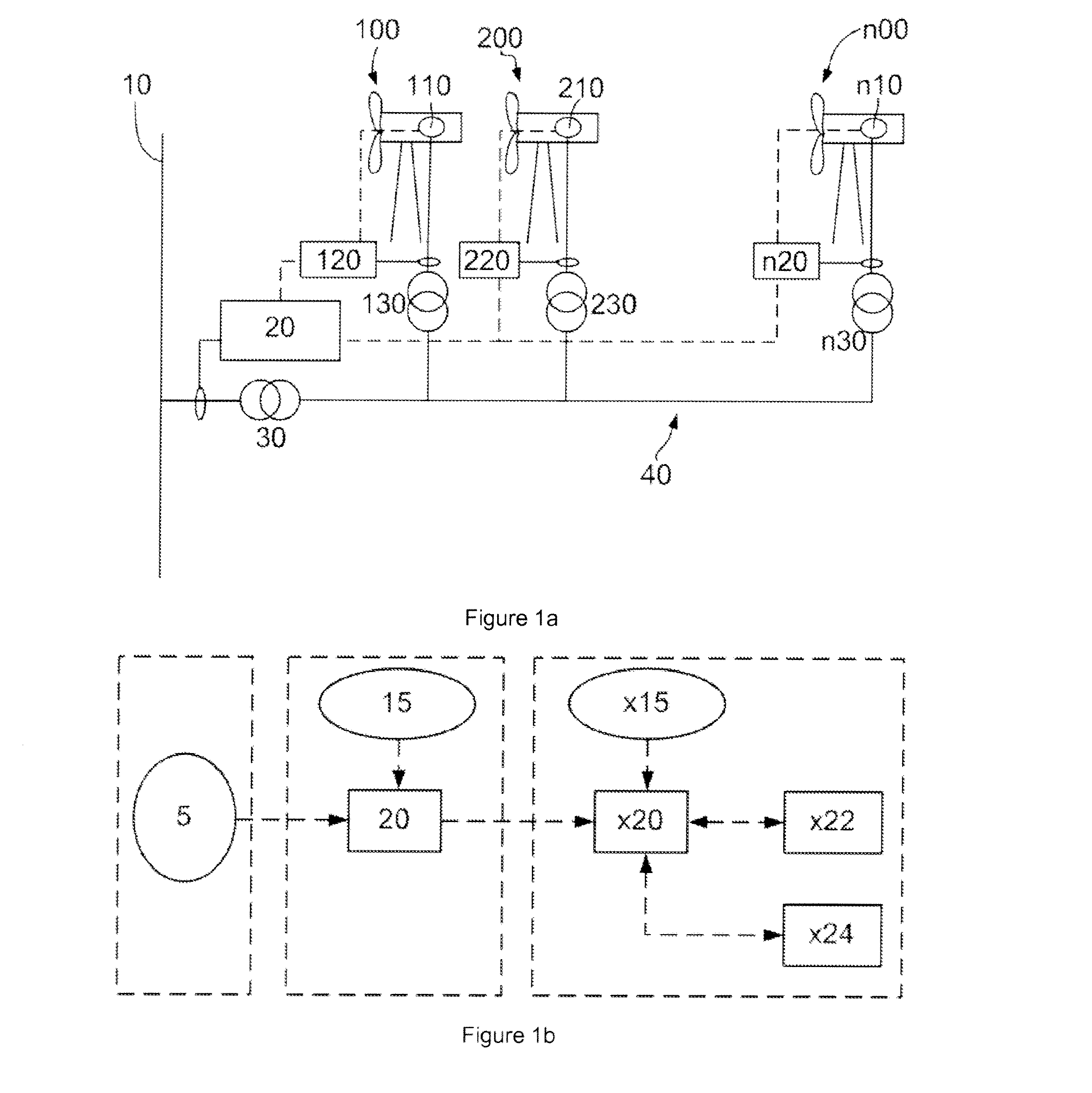
[0040]FIG. 1a schematically illustrates a wind park comprising n wind turbines, 100, 200 . . . n00. At least a portion of the n wind turbine...


PUM


Abstract

The present invention relates to a method of reactive power regulation in a wind turbine comprising a local reactive power control system adapted to operate in a central control mode and a local control mode, a method of reactive power regulation in a wind park connected to an electrical grid, and to a wind park.

Description

[0001]The present invention relates to a method for reactive power regulation in a wind park, a method of reactive power regulation in a wind turbine and to a wind park.BACKGROUND ART[0002]With the increased use of wind energy for electricity generation, grid operators (TSO's or Transmission System Operators) have introduced stricter requirements for wind park operators with respect to active and reactive power generation in support of the grid. For example, wind park operators may be requested to not always generate maximum active power available depending on wind conditions. Also, in accordance with some grid codes, wind parks have to support the grid during a voltage drop and not e.g. disconnect from the grid.[0003]In this respect, it is known to vary the reactive power generated in a wind park in accordance with a grid voltage at a Point of Common Coupling (PCC). It is also known to vary the active power generated in a wind park in accordance with a measured grid frequency.[0004...

Claims


Application Information

Patent Timeline
Patent Type & Authority Applications(United States)
IPC IPC(8): F03D7/00F03D9/00
CPCF03D9/005F03D7/00H02J3/1842H02J3/1892H02J3/50F03D7/0284F03D7/048F03D9/257H02J2300/28H02J3/381Y02E10/76Y02E10/72Y02E40/20H02J3/472
Inventor MATA DUMENJO, MONTSERRATCARULLA PIERA, JORDIGOMIS, ORIOL
Owner GE RENEWABLE TECH WIND BV
Why Eureka
Try Eureka