Eureka AIR delivers breakthrough ideas for toughest innovation challenges, trusted by R&D personnel around the world.

Determining surface wetting of rock with changing well fluids

a technology of surface wetting and well fluid, which is applied in the direction of wave based measurement system, instrument, reradiation, etc., can solve the problems of hydraulic cement compositions that do not bond well to oil-wetted surfaces, proportional decrease in the shear bond strength of the interface, and unsatisfactory effects

Inactive Publication Date: 2014-03-06
HALLIBURTON ENERGY SERVICES INC
View PDF0 Cites 33 Cited by
  • Summary
  • Abstract
  • Description
  • Claims
  • Application Information

AI Technical Summary

Benefits of technology

The invention provides methods and devices for measuring the wetting of surfaces in a well using electrical impedance spectroscopy (EIS). These methods allow for the detection of surface wetting in the downhole environment, providing valuable information on the status of well tools and equipment. The invention offers a novel way to inspect the condition of well tools and equipment during well drilling and well stimulation operations, reducing the risk of damage and ensuring safe and successful well construction.

Problems solved by technology

Some well fluids can form such a film or layer on a downhole surface, which can have undesirable effects.
If first wetted with an oleaginous film, however, the oleaginous film on the metallic surface blocks the metal surface from being wettable with a water-based fluid.
Hydraulic cement compositions do not bond well to oil-wetted surfaces.
Because of this incomplete surface bonding, there is a proportional decrease in the shear bond strength of the interface between the set cement sheath and the formation / tubular surfaces and premature interfacial de-bonding might occur under the loads experienced during the course of the well operations.
This may have unwanted consequences such as interzonal communication, loss of production, and sustained casing pressure.
Any of these can be detrimental to the safety and economics of hydrocarbon production from the well.
The systems of well fluids and operations with well fluids can be highly complex and difficult to predict.

Method used


Image

  • Determining surface wetting of rock with changing well fluids
  • Determining surface wetting of rock with changing well fluids
  • Determining surface wetting of rock with changing well fluids

Examples


Embodiment Construction

Definitions and Usages

[0060]Interpretation

[0061]The words or terms used herein have their plain, ordinary meaning in the field of this disclosure, except to the extent explicitly and clearly defined in this disclosure or unless the specific context otherwise requires a different meaning.

[0062]If there is any conflict in the usages of a word or term in this disclosure and one or more patent(s) or other documents that may be incorporated by reference, the definitions that are consistent with this specification should be adopted.

[0063]The words “comprising,”“containing,”“including,”“having,” and all grammatical variations thereof are intended to have an open, non-limiting meaning. For example, a composition comprising a component does not exclude it from having additional components, an apparatus comprising a part does not exclude it from having additional parts, and a method having a step does not exclude it having additional steps. When such terms are used, the compositions, apparatu...


PUM


Abstract

Methods and apparatuses for determining surface wetting of a rock material with changing well fluids. In general, the methods according to the invention include measuring electrical impedance spectroscopy (“EIS”) for a system simulating downhole conditions for the wetting of a surface. Methods and apparatuses for making EIS measurements model double-layer capacitance at a downhole surface in a well, from which the nature and quantification of the wetting of the surface can be inferred.

Description

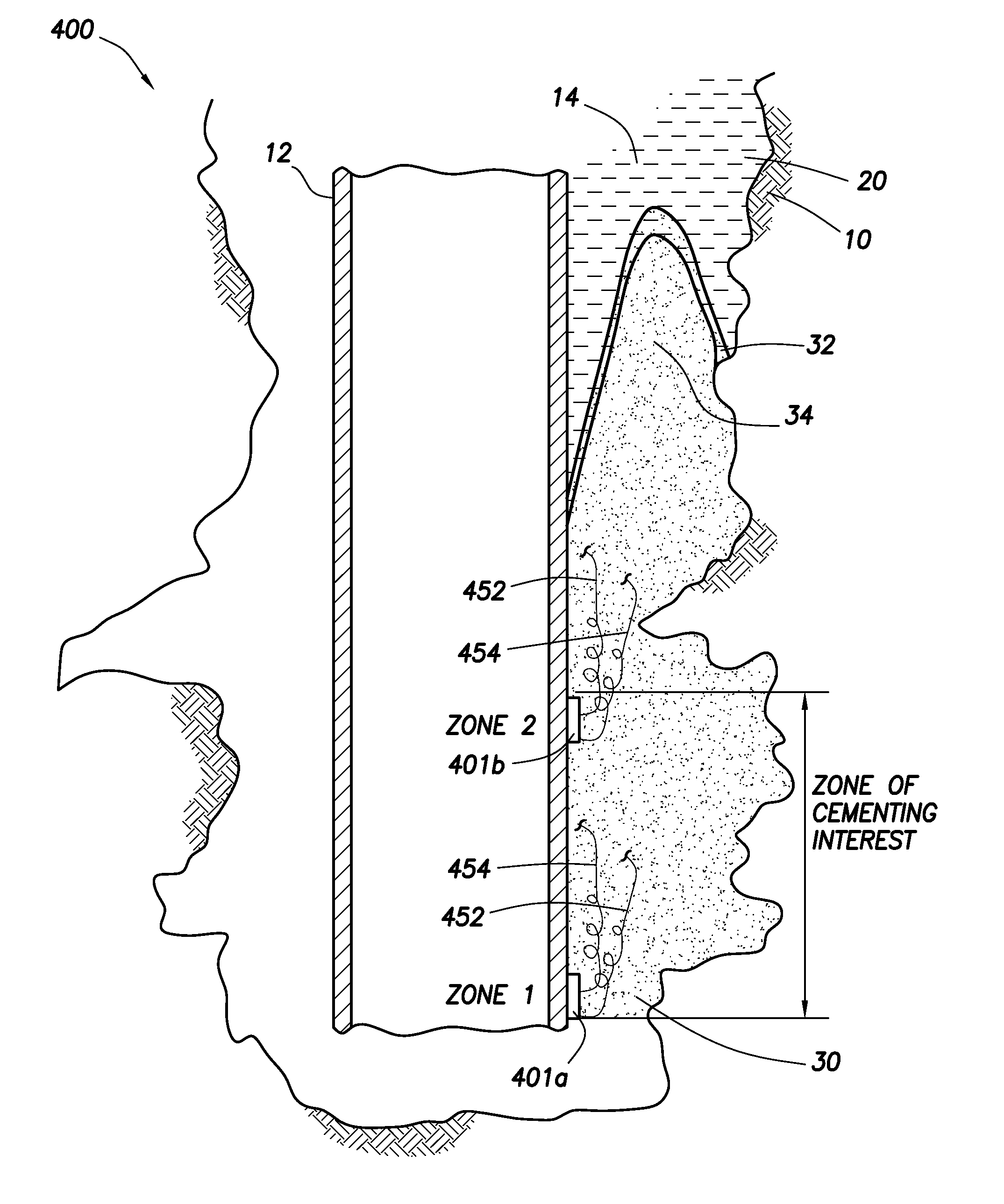
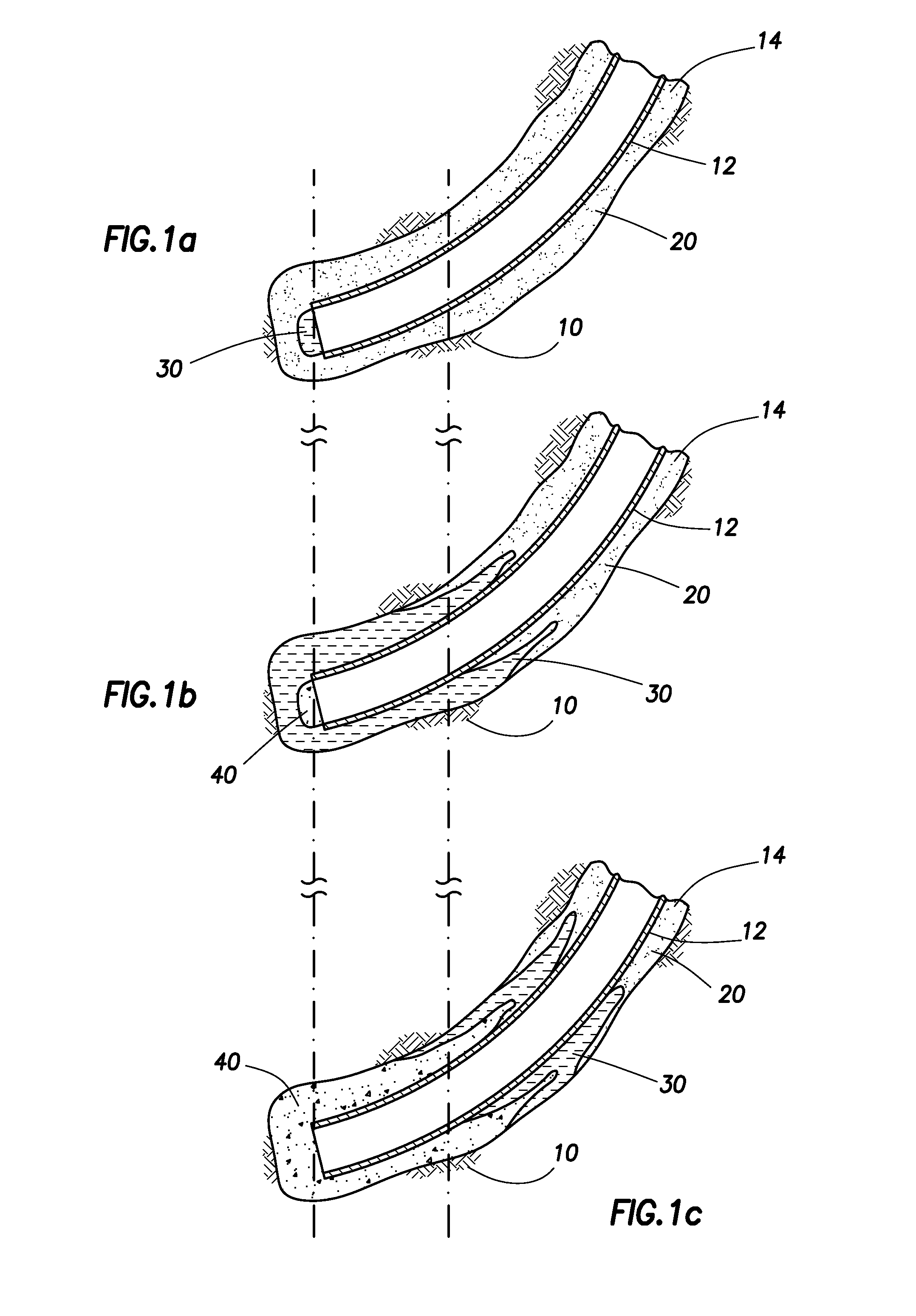
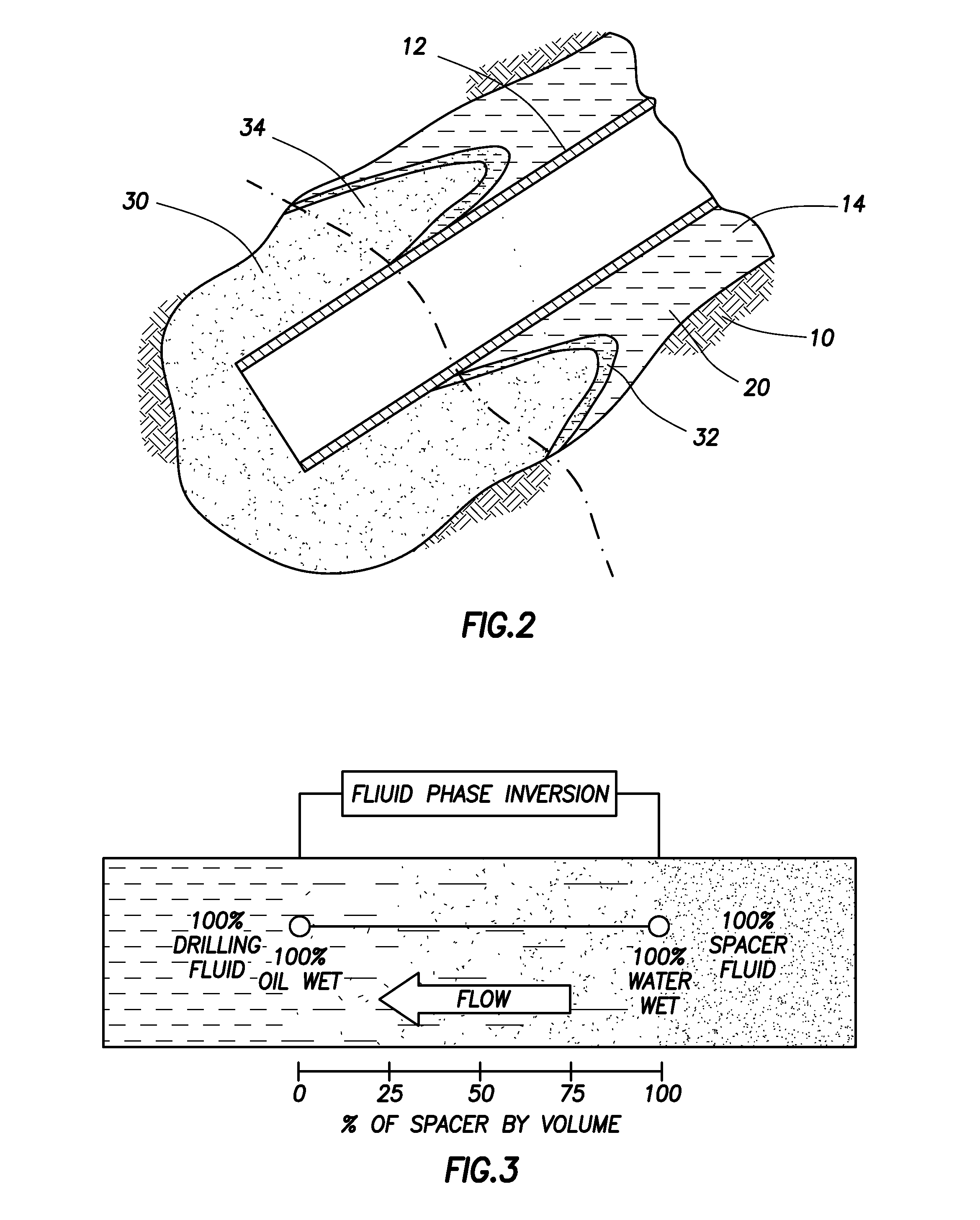
CROSS-REFERENCE TO RELATED APPLICATIONS[0001]Not applicable.TECHNICAL FIELD[0002]The inventions are in the field of producing crude oil or natural gas from subterranean formations. More specifically, the inventions generally relate to methods and apparatuses for determining surface wetting with changing of well fluids. Applications of the methods and apparatuses include without limitation, for example, the designing of spacer or inverter fluids and the field-operational parameters for wellbore cleanout and fluid separation prior to cementing operations in a well.BACKGROUND ART[0003]To produce oil or gas, a well is drilled into a subterranean formation that is an oil or gas reservoir.Well Servicing and Well Fluids[0004]Generally, well services include a wide variety of operations that may be performed in oil, gas, geothermal, or water wells, such as drilling, cementing, completion, and intervention. Well services are designed to facilitate or enhance the production of desirable fluid...

Claims


Application Information

Patent Timeline
IPC IPC(8): G01V3/18
CPCG01N13/00G01N27/026
Inventor PINDIPROLU, SAIRAM KSGRAY, DENNIS WILLIEPALLA, VENKATA GOPALA RAO
Owner HALLIBURTON ENERGY SERVICES INC
Why Eureka
Eureka Blog
Learn More