
Apparatus and method for acquiring information about light-field data

a technology of light-field data and apparatus, which is applied in the field of apparatus and a method for acquiring information about light-field data, can solve problems such as deterioration of accuracy

Active Publication Date: 2014-03-06
CANON KK
View PDF2 Cites 61 Cited by
  • Summary
  • Abstract
  • Description
  • Claims
  • Application Information

AI Technical Summary

Benefits of technology

This patent describes an apparatus and method for acquiring information about light-field data. It involves a beam splitter that splits light from an object into two light beams, an image sensor that detects one of the beams to capture an image, and a light-field sensor that detects the other beam through a lenslet array. The light-field sensor includes a plurality of lenslets that are moved to maintain a conjugate relationship with the pupil of the lens unit, where the second beam passes through the lens unit. This allows for the detection of the second beam and the acquisition of information about the light-field data of the object. The technical effect is the efficient and effective acquisition of information about light-field data.

Problems solved by technology

Due to a zooming operation, when the state of the image formation is changed, the change may cause the deterioration of the accuracy.

Method used


Image

  • Apparatus and method for acquiring information about light-field data
  • Apparatus and method for acquiring information about light-field data
  • Apparatus and method for acquiring information about light-field data

Examples


Embodiment Construction

[0021]Embodiments according to the present invention will be described below with reference to the attached drawings.

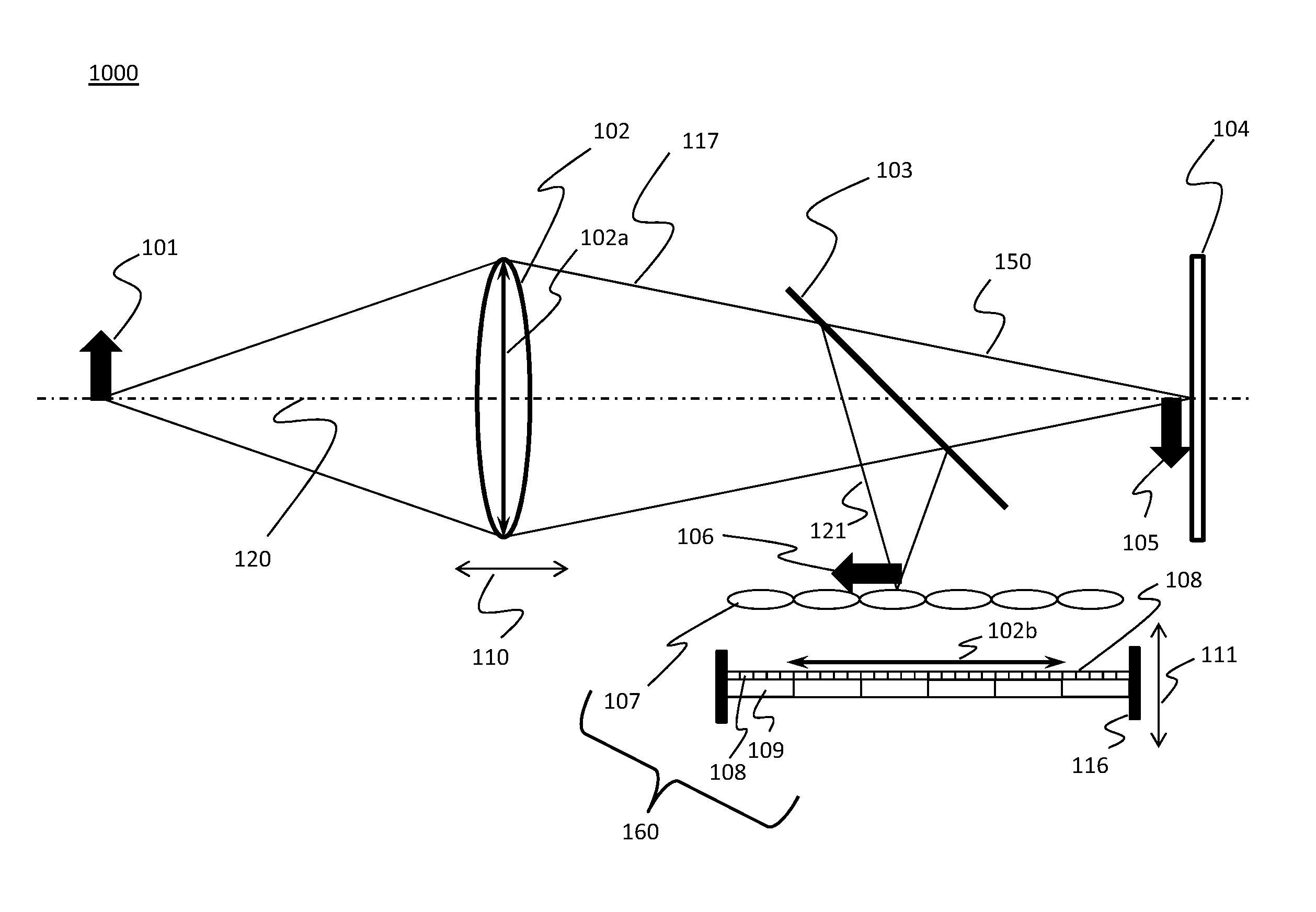
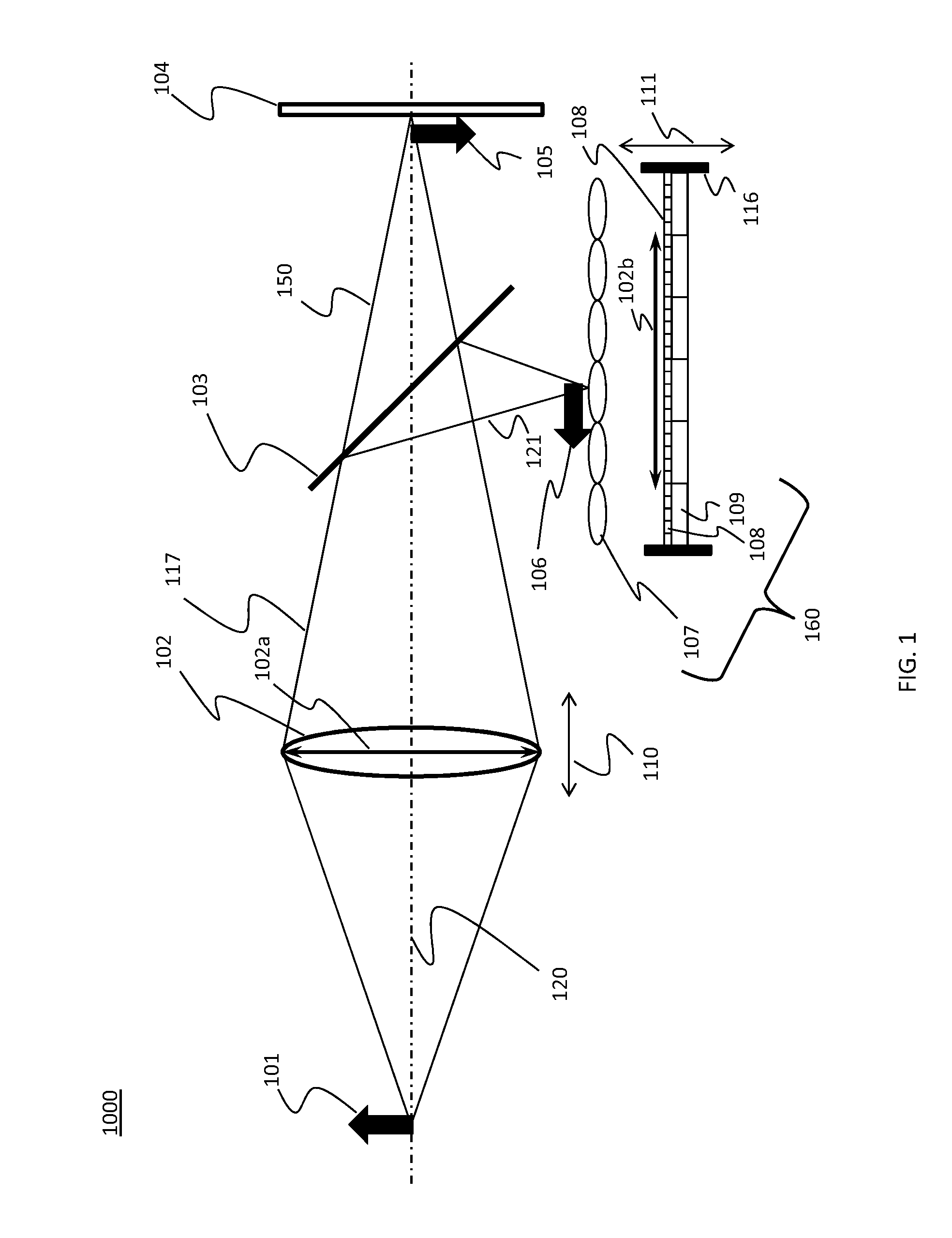
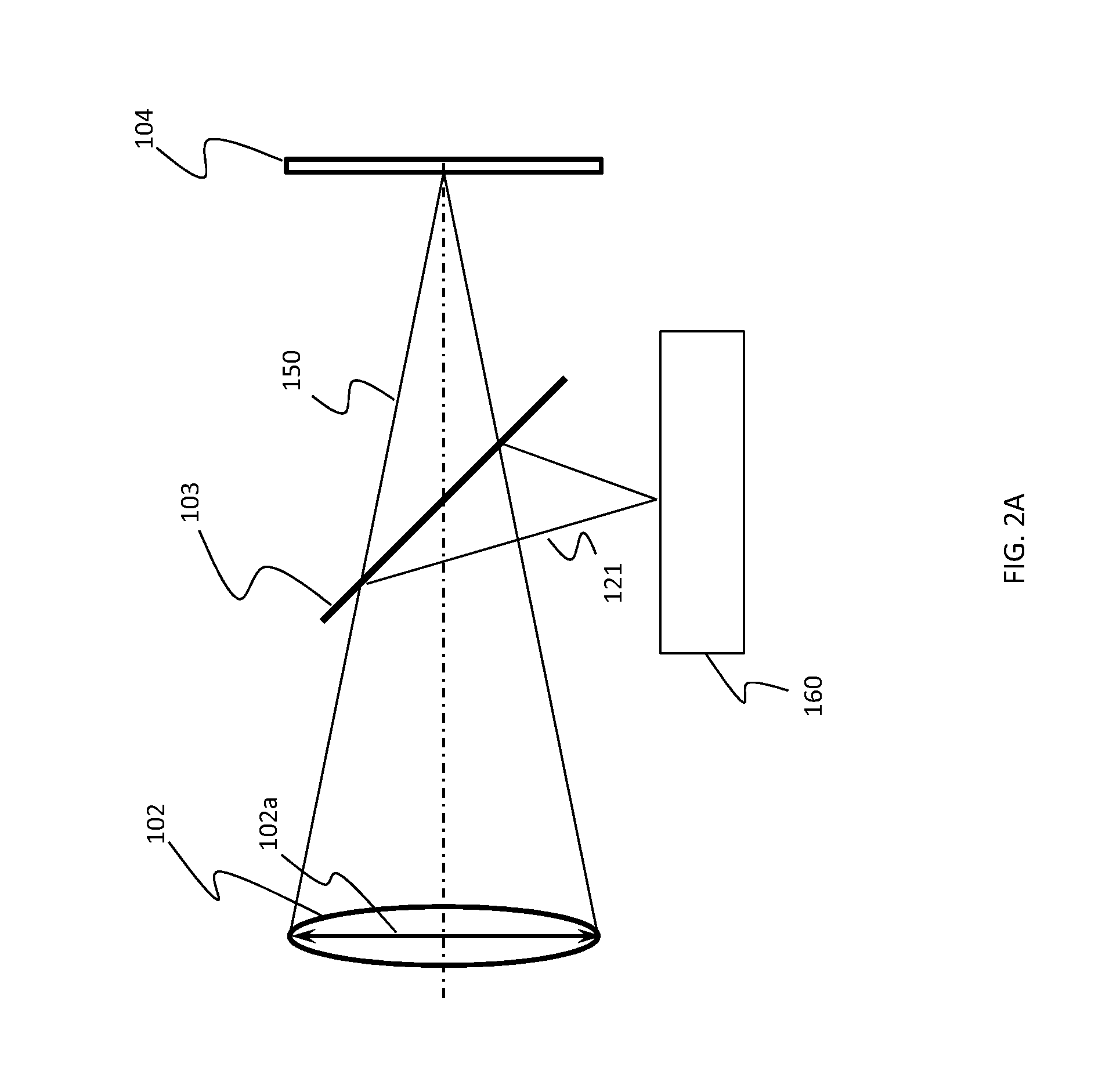
[0022]A configuration of a light-field data acquisition device 1000 is illustrated in FIG. 1. A lens unit 102 for forming an image of an object 101 and an image sensor 104 are placed along an optical axis 120. In the device 1000, the lens unit can include a plurality of lenses for, for example, an auto-focusing function and a zooming function. The lens unit 102 is drawn as one lens in FIG. 1 for abbreviation.

[0023]A reference 102a denotes a pupil of the lens unit. The pupil is an image of an aperture stop of the lens unit 102. The pupil 102a may be called an exit pupil technically. The lens unit 102 is related to resolution and field angle of the lens unit of the device 1000.

[0024]A beam splitter 103 (e.g., dichroic beam splitter, 50:50 beam splitter, 80:20 beam splitter, 90:10 beam splitter, and polarization beam splitter) can separate radiation 121 (e.g., near infra...


PUM


Abstract

An apparatus to acquire information about light-field data includes: a beam splitter configured to split light, through a lens unit which is connected to the apparatus, from an object into a first light beam and a second light beam; an image sensor configured to detect the first light beam to form an image of the object; and a light-field sensor, including a lenslet array and a detecting unit to detect the second light beam through the lenslet array, configured to acquire information about the light-field data, the lenslet array including a plurality of lenslets, wherein a first position where the detecting unit is provided is conjugate to a second position of a pupil of the lens unit.

Description

BACKGROUND OF THE INVENTION[0001]1. Field of the Invention[0002]In one aspect, the present invention is related to an apparatus and a method for acquiring information about light-field data and especially related to a light-filed camera.[0003]2. Description of the Related Art[0004]A light-filed camera is disclosed in U.S. Pat. No. 7,936,392. By using a micro-lens (i.e. lenslet) array and a photo-sensor array, the light-field camera can not only capture how much light accumulates at each spatial location on an image plane, but also obtain information about a direction from which the light arrived at the micro-lens array.[0005]The micro-lens array is placed in front of the photo-sensor array along an optical axis to sample data related to the direction of the light. The accuracy of the direction depends on a state of an image formation on the photo-sensor array.[0006]Due to a zooming operation, when the state of the image formation is changed, the change may cause the deterioration of...

Claims


Application Information

Patent Timeline
Patent Type & Authority Applications(United States)
IPC IPC(8): H04N5/225
CPCG03B13/20G03B35/10H04N23/957H04N23/60H04N23/951H04N23/21H04N5/33
Inventor MIYAWAKI, MAMORU
Owner CANON KK
Learn More