
Liquid crystal display device

Inactive Publication Date: 2014-03-06
JAPAN DISPLAY INC
View PDF14 Cites 1 Cited by
  • Summary
  • Abstract
  • Description
  • Claims
  • Application Information

AI Technical Summary

Benefits of technology

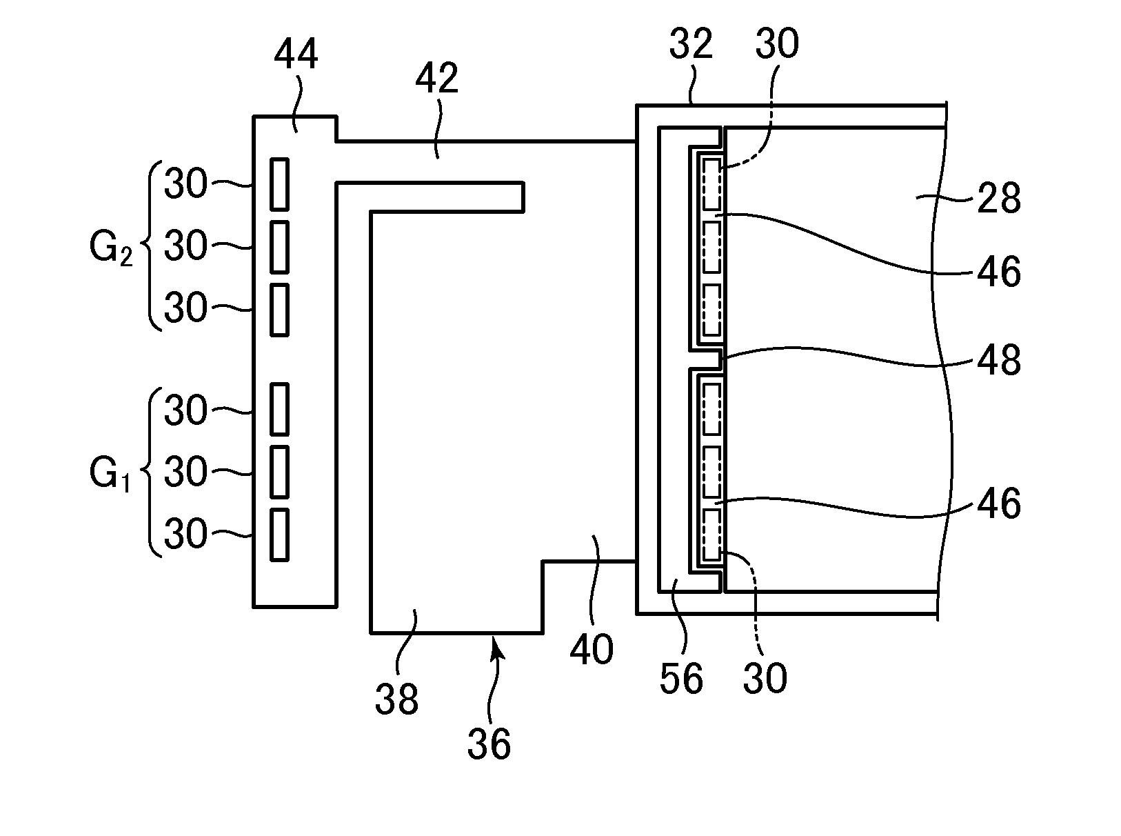
The invention relates to a liquid crystal display device that aims to prevent damage to the display panel caused by a reduction in frame strength. The device includes a liquid crystal display panel and an edge light type backlight. The backlight includes a light guide plate and plural light-emitting elements arranged to face the end face of the light guide plate. The frame is attached to the peripheral edge of the liquid crystal display panel and includes plural recesses recessed from its inner surface and opposite surface. Protrusions are formed between adjacent recesses. The invention prevents damage to the liquid crystal display panel by suppressing the reduction of frame strength. The protrusions are positioned between the recesses to avoid short circuits and effectively use space.

Problems solved by technology

Thus, a wall can not be formed between the adjacent light-emitting elements, and there is a fear that the strength of the frame is reduced.
The liquid crystal display panel becomes liable to be damaged by the reduction of the strength of the frame.

Method used


Image

  • Liquid crystal display device
  • Liquid crystal display device
  • Liquid crystal display device

Examples


Embodiment Construction

[0031]Hereinafter, an embodiment of the invention will be described with reference to the drawings.

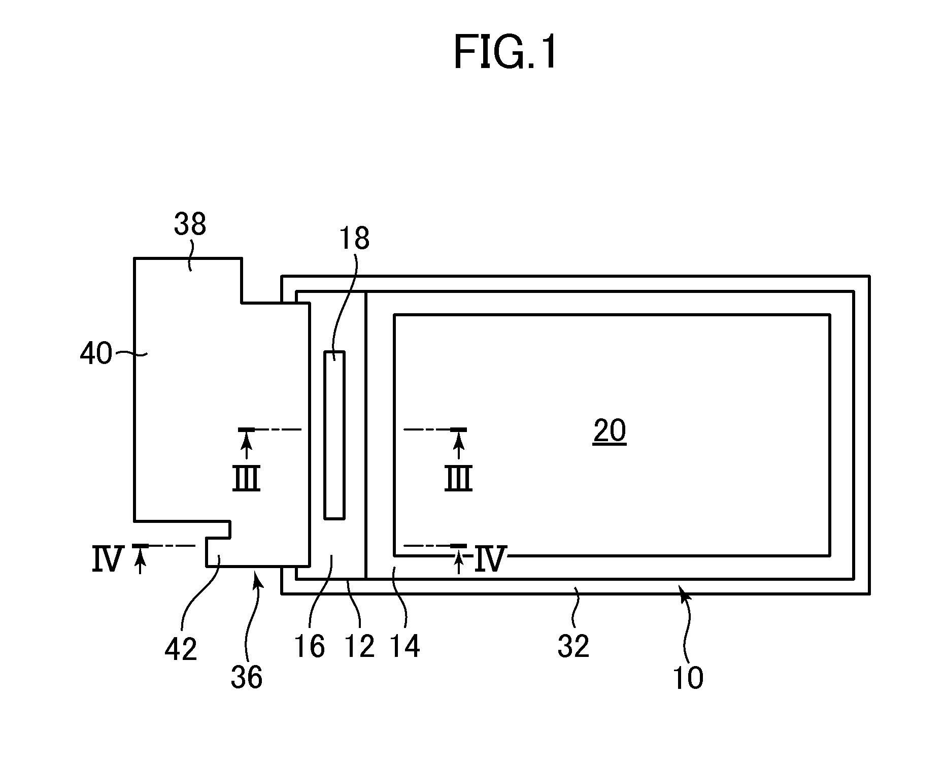
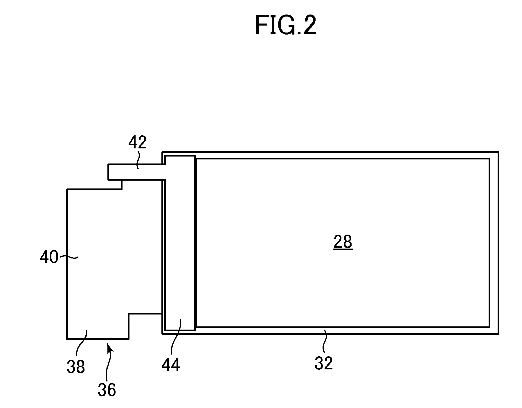
[0032]FIG. 1 is a front surface view of a liquid crystal display device of the embodiment of the invention. FIG. 2 is aback surface view of the liquid crystal display device of the embodiment of the invention. FIG. 3 is a III-III line sectional view of the liquid crystal display device shown in FIG. 1. FIG. 4 is a IV-IV line sectional view of the liquid crystal display device shown in FIG. 1.

[0033]The liquid crystal display device includes a liquid crystal display panel 10. The liquid crystal display panel 10 includes a pair of boards 12 and 14 (both are made of, for example, glass boards), and not-shown liquid crystal intervenes between both. The one board 12 is a TFT (Thin Film Transistor) board (or an array board) including not-shown thin film transistors, pixel electrodes, wiring and the like, and the other board 14 is a color filter board.

[0034]The one board 12 of the liquid cryst...


PUM


Abstract

In a liquid crystal display device, adjacent light-emitting elements of adjacent different groups are not connected in series but are arranged with an interval. Adjacent light-emitting elements of the same group are arranged with an interval shorter than the interval between the adjacent light-emitting elements of the adjacent different groups. The frame includes plural recesses recessed from an inner peripheral surface facing the light guide plate and recessed also from a surface opposite to the liquid crystal display panel. A protrusion is relatively formed between the adjacent recesses. The light-emitting elements of any one of the groups are housed in one of the recesses and the light-emitting elements of the plural groups are respectively housed in the plural recesses. A protrusion is positioned between the adjacent light-emitting elements of the adjacent different groups.

Description

CROSS-REFERENCE TO RELATED APPLICATION[0001]The present application claims priority from Japanese application JP2012-189871 filed on Aug. 30, 2012, the content of which is hereby incorporated by reference into this application.BACKGROUND OF THE INVENTION[0002]1. Field of the Invention[0003]The present invention relates to a liquid crystal display device.[0004]2. Description of the Related Art[0005]A backlight of a liquid crystal display device includes a light guide plate for converting a point light source into a surface light source, and plural light-emitting elements are arranged in a line so as to face an end face of the light guide plate (JP 2010-62016A). Light emitted from the light-emitting element as the point light source is incident on the end face of the light guide plate, and outgoes to a liquid crystal display panel from the surface of the light guide plate by reflection. The light-emitting elements and the light guide plate are housed in a frame.[0006]The frame to hous...

Claims


Application Information

Patent Timeline
IPC IPC(8): F21V8/00
CPCG02B6/0083G02B6/0091G02B6/0068
Inventor OOHIRA, EIJI
Owner JAPAN DISPLAY INC
Learn More