Optical Velocimetry Systems and Methods for Determining the Velocity of a Body Using Fringes Generated by a Spatial Light Modulator

a spatial light modulator and optical velocity technology, applied in the field of optical velocity systems, can solve the problems of increasing the cost of the ldv system, requiring further optical alignment procedures, and unable to determine the propagation direction of the body through the interference fringes from the measured intensity of scattered ligh

Inactive Publication Date: 2014-03-06
DANTEC DYNAMICS
View PDF5 Cites 12 Cited by
  • Summary
  • Abstract
  • Description
  • Claims
  • Application Information

AI Technical Summary

Benefits of technology

[0014]In another feature, the spatial light modulator is adapted to operate in reflectance. The spatial light modulator has reflective regions arranged along a given direction and each reflective region is positioned between two non-reflective regions. The reflective regions each substantially reflect light incident thereon and the non-reflective regions each prevent reflection of light thereon.
[0044]In a further feature, the step of adjusting the optical properties of the spatial light modulator causes a generation of opaque regions and transmissive regions on the spatial light modulator. The opaque regions are arranged along a given direction and each opaque region are positioned between two transmissive regions. The opaque regions each substantially prevent light from propagating therethrough and the transmissive regions each allow light to propagate therethrough.
[0045]In still another feature, the step of adjusting the optical properties of the spatial light modulator causes a generation of reflective regions and non-reflective regions on the spatial light modulator. The reflective regions are arranged along a given direction and each reflective region is positioned between two non-reflective regions. The reflective regions each substantially reflect light incident thereon and the non-reflective regions each prevent reflection of light thereon.
[0061]In a further feature, the method further includes a step of propagating a modulated light beam projected by the spatial light modulator through a 4f optical system positioned between the spatial light modulator and the measurement volume for reducing back reflections and scattering.

Problems solved by technology

Therefore, the propagation direction of the body through the interference fringes cannot be determined from the measured intensity of the scattered light.
However, such a technique requires additional pieces of equipment such as the Bragg cell for example, which increases the cost for the LDV system in addition to requiring further optical alignment procedures which are time-consuming.
Therefore, this feature limits the choice of adequate light sources for generating the interference fringes, and non-coherent light sources cannot be used for example.
Furthermore, such LDV systems may not be adequate for specific applications such as some medical applications, due to laser safety issues.
As for the LDV system, the generated fringes are stationary and the same problem of directional ambiguity exists.
Furthermore, the fringe spacing of the fringes generated using a Ronchi grating system is fixed and may not be changed.
In order to change the fringe spacing, a different Ronchi grating must be used, which increases the cost.
Furthermore, changing the Ronchi gratings and aligning the optical system thereafter are time-consuming steps.
Furthermore, these two approaches tend to afford only limited versatility.
For example, orienting the fringes generated by an LDV system or a Ronchi grating system requires additional machinery, which also increases the overall cost for such systems.

Method used


Image

  • Optical Velocimetry Systems and Methods for Determining the Velocity of a Body Using Fringes Generated by a Spatial Light Modulator
  • Optical Velocimetry Systems and Methods for Determining the Velocity of a Body Using Fringes Generated by a Spatial Light Modulator
  • Optical Velocimetry Systems and Methods for Determining the Velocity of a Body Using Fringes Generated by a Spatial Light Modulator

Examples


Embodiment Construction

[0109]The description which follows, and the embodiments described therein are provided by way of illustration of an example, or examples of particular embodiments of principles and aspects of the present invention. These examples are provided for the purposes of explanation and not of limitation, of those principles of the invention. In the description that follows, like parts are marked throughout the specification and the drawings with the same respective reference numerals.

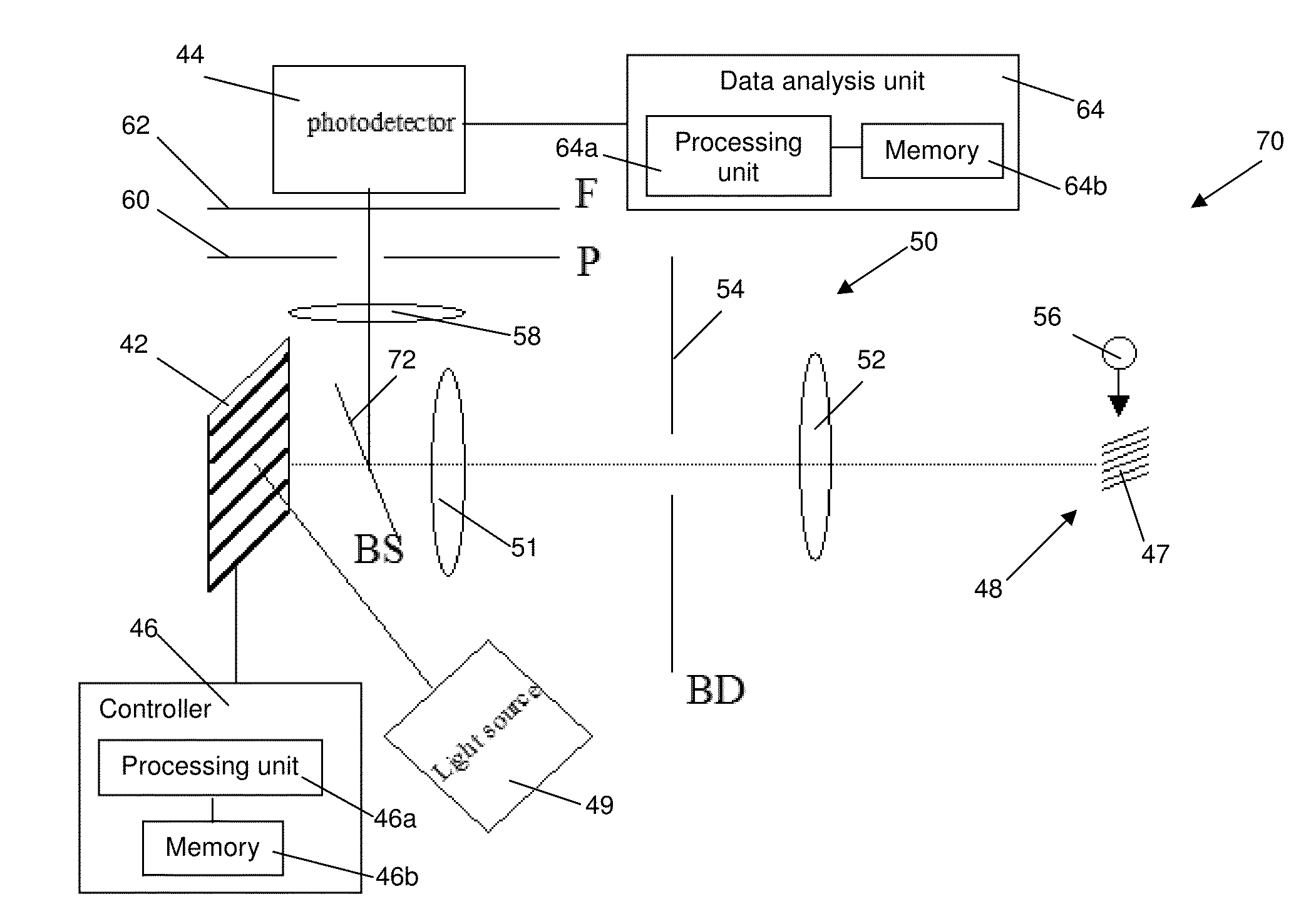
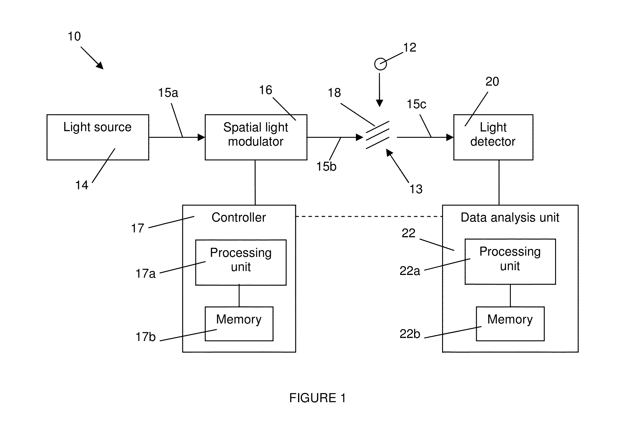
[0110]Referring to FIG. 1, there is shown conceptually the main components of a velocimetry system 10 for determining the velocity of a body 12 passing through a measurement chamber or volume 13 (also known as an interrogation area or region). The measurement volume 13 may have a variety of shapes (e.g. ellipsoid or cuboid). The body 12 may be a particle (for instance, a smoke particle, or a particle entrained in a fluid), the surface of a moving body, a droplet, a microscopic object or the like. Moreover, the...


PUM


Abstract

A velocimetry system for measuring the velocity of a moving body propagating through a measurement volume includes a light source for emitting a light beam, a controller for generating a modulation pattern corresponding to a desired set of fringes to be generated in the measurement volume, and a spatial light modulator operatively connected to the controller to receive therefrom the modulation pattern. The spatial light modulator is configured to spatially modulate the light beam according to the modulation pattern in order to generate the desired set of fringes in the measurement volume. Also provided are a light detector for measuring the energy of the light scattered by the moving body as it intersects the fringes, and a data analysis unit operatively connected to the light detector and adapted to determine the velocity of the moving body from at least one fringe characteristic and the energy of the scattered light measured.

Description

TECHNICAL FIELD[0001]The present invention relates to the field of velocimeters, and more particularly to optical velocimetry systems.BACKGROUND OF THE INVENTION[0002]Optical velocimetry systems or velocimeters are non-intrusive instruments for measuring velocities of particles, moving surfaces, etc. An optical velocimetry system creates fringes made of bright planes of light alternating with dark planes within a measurement volume through which particles entrained in fluids or on moving surfaces propagate. The light scattered from the particles that bisect the fringes is detected and measured to determine the velocity of the particles.[0003]In a Laser Doppler Velocimetry (LDV) system, the fringes are created by intersecting two laser beams together to generate interference fringes in a measurement volume. While a body propagates through the generated interference fringes, scattered light is generated and the intensity variation of the scattered light is substantially independent of...

Claims


Application Information

Patent Timeline
Patent Type & Authority Applications(United States)
IPC IPC(8): G01P3/36
CPCG01P3/68G01S17/58
Inventor TAURO, SANDEEPMULLER, JEAN-MARC
Owner DANTEC DYNAMICS
Why Eureka
Try Eureka