Illumination system

a technology of illumination system and insulating plate, which is applied in the field of illumination, can solve the problems of reduced life of led, difficult to package in a convenient manner, and easy damage, and achieve the effect of easy inclusion

Active Publication Date: 2014-03-06
MOLEX INC
View PDF16 Cites 27 Cited by
  • Summary
  • Abstract
  • Description
  • Claims
  • Application Information

AI Technical Summary

Benefits of technology

[0004]An illumination system is disclosed that includes a receiver which is mounted on a support surface that acts as a heat sink, a cover and an LED assembly. The LED assembly is attached to the cover and seats within the receiver. The receiver has terminals attached thereto for providing power to the LED assembly. The LED assembly includes a housing which enables potting material to be easily included in the assembly during manufacturing. When the LED assembly is attached to the receiver, the terminals on the LED assembly mate with the terminals on the receiver.

Problems solved by technology

One long standing issue with LEDs, however, is that they are susceptible to damage if not protected from heat.
Generally speaking, a LED will have a reduced life and less pleasing color output as the operating temperature of the LED increases.
In addition to the issues with heat, the ability of an LED to act as a point source provides desirable lighting properties, but can be challenging to package in a manner that is convenient.
Often LEDs are a permanent part of a fixture and while the life of a LED is quite long, there is still the problem of having to replace an entire fixture if the LED fails prematurely or even after the 20-50,000 hours of life.

Method used


Image

  • Illumination system
  • Illumination system
  • Illumination system

Examples


Embodiment Construction

[0023]While the invention may be susceptible to embodiment in different forms, there is shown in the drawings, and herein will be described in detail, a specific embodiment with the understanding that the present disclosure is to be considered an exemplification of the principles of the invention, and is not intended to limit the invention to that as illustrated and described herein.

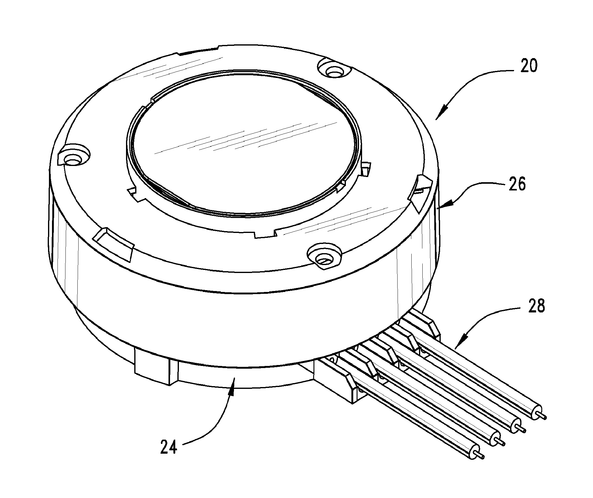
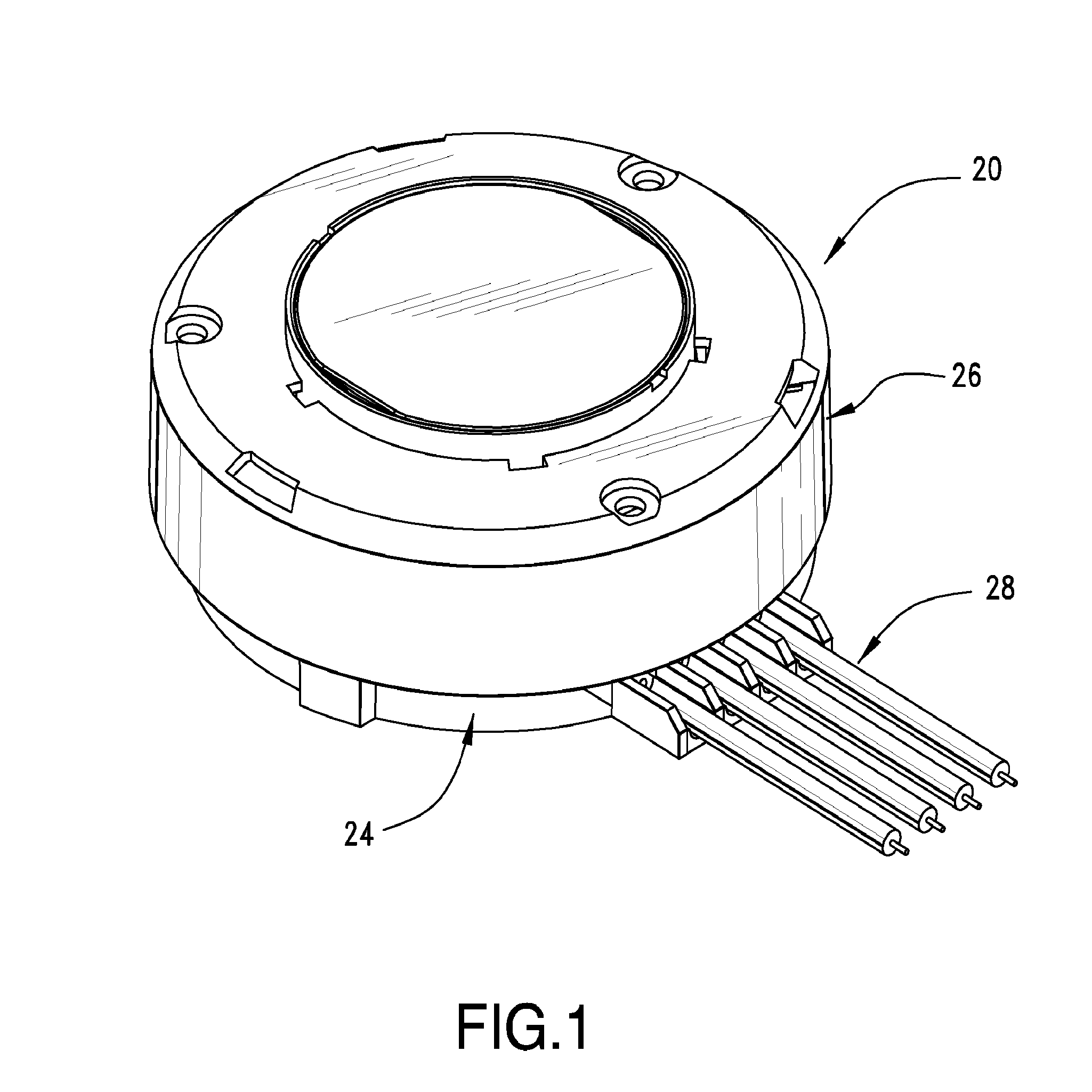
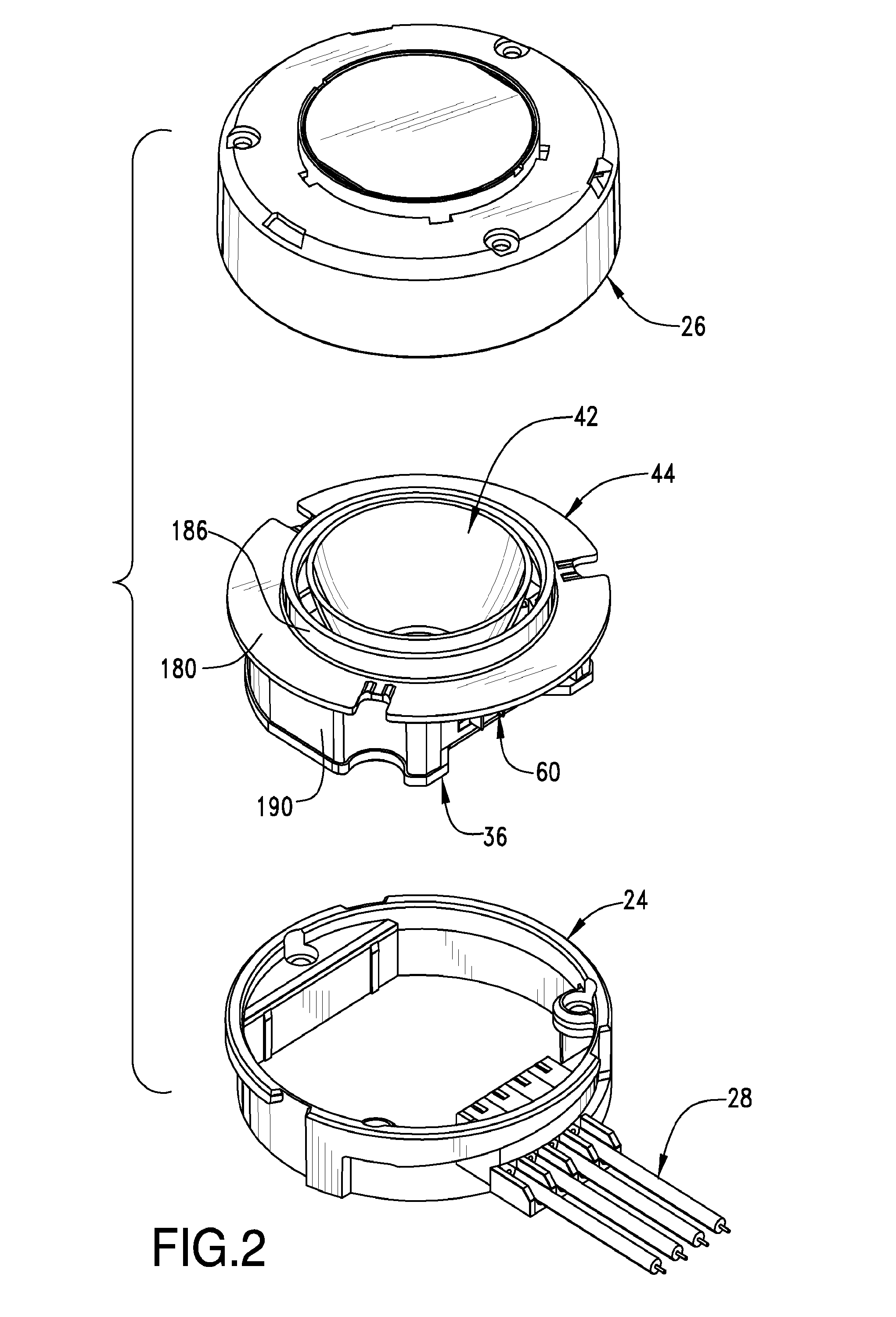
[0024]A light module 20 is disclosed for mounting in a receiver 24. While the terms lower, upper and the like are used for ease in describing the light module 20, it is to be understood that these terms do not denote a required orientation for use of the light module 20. The light module 20 can be configured to provide an aesthetically pleasing appearance or if desired, can be configured to support optional aesthetic covers. As can be appreciated, other configurations with different appearances, such as square or some other shape light modules, as well as with different heights and dimensions are possibl...


PUM


Abstract

An illumination system may include a receiver which is mounted on a support surface, such as a heat sink, and a light module that may include a cover and an LED assembly. The LED assembly is rotateably attached to the cover and seats within the receiver. The receiver may have touch-safe terminals attached thereto for providing power to the LED assembly. The LED assembly may include a cup which enables potting material to be easily included in the assembly during manufacturing. When the LED assembly is attached to the receiver, blades on the LED assembly mate with the terminals on the receiver.

Description

RELATED APPLICATIONS[0001]This application claims priority to United States Provisional Application No. 61 / 478,701, filed Apr. 25, 2011, which is incorporated herein by reference in its entirety.FIELD OF THE INVENTION[0002]The present invention relates to field of illumination, more specifically to an illumination system having a light emitting diode that is capable of being attached to a heat sink.BACKGROUND OF THE INVENTION[0003]A number of solid state lighting technologies exist and one of the more promising types is a light emitting diode (LED). LEDs have dramatically improved and now can provide high efficiencies and high lumen output. One long standing issue with LEDs, however, is that they are susceptible to damage if not protected from heat. Generally speaking, a LED will have a reduced life and less pleasing color output as the operating temperature of the LED increases. In addition to the issues with heat, the ability of an LED to act as a point source provides desirable l...

Claims


Application Information

Patent Timeline
Patent Type & Authority Applications(United States)
IPC IPC(8): F21V29/00F21V7/00F21V13/04F21V15/01
CPCF21V29/22F21V13/04F21V7/00F21V15/01F21V17/06F21V17/12F21V19/0035F21V23/06F21Y2115/10F21V29/50F21V29/503
Inventor MCGOWAN, DANIEL B.ZADEREJ, VICTORCOLE, MARK A.
Owner MOLEX INC
Why Eureka
Try Eureka