
DC power source device and power conversion method

a technology of dc power source and power conversion method, which is applied in the direction of electric variable regulation, process and machine control, instruments, etc., can solve the problems of increasing the efficiency of dc/dc converter, circuit becomes complicated, and the reduction of on-resistance and saturation voltage are close to limitations technically, so as to improve the power factor, prevent the effect of circuit complication, and stable off-sta

Active Publication Date: 2014-03-06
MITSUBISHI ELECTRIC CORP
View PDF10 Cites 13 Cited by
  • Summary
  • Abstract
  • Description
  • Claims
  • Application Information

AI Technical Summary

Benefits of technology

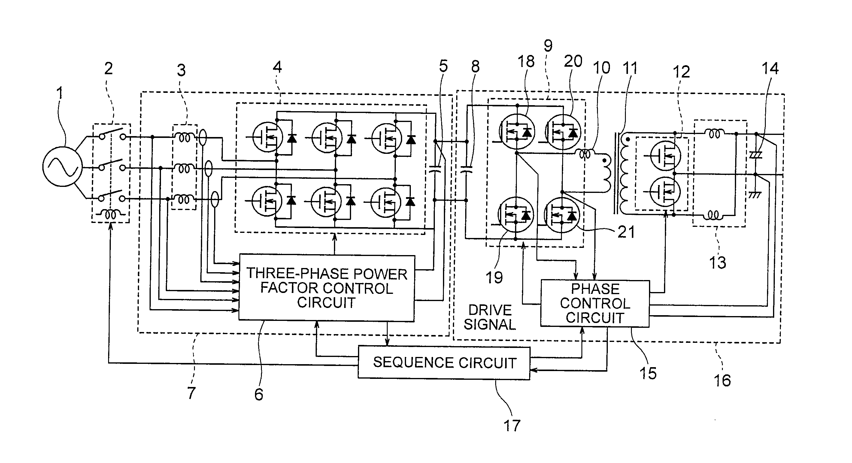
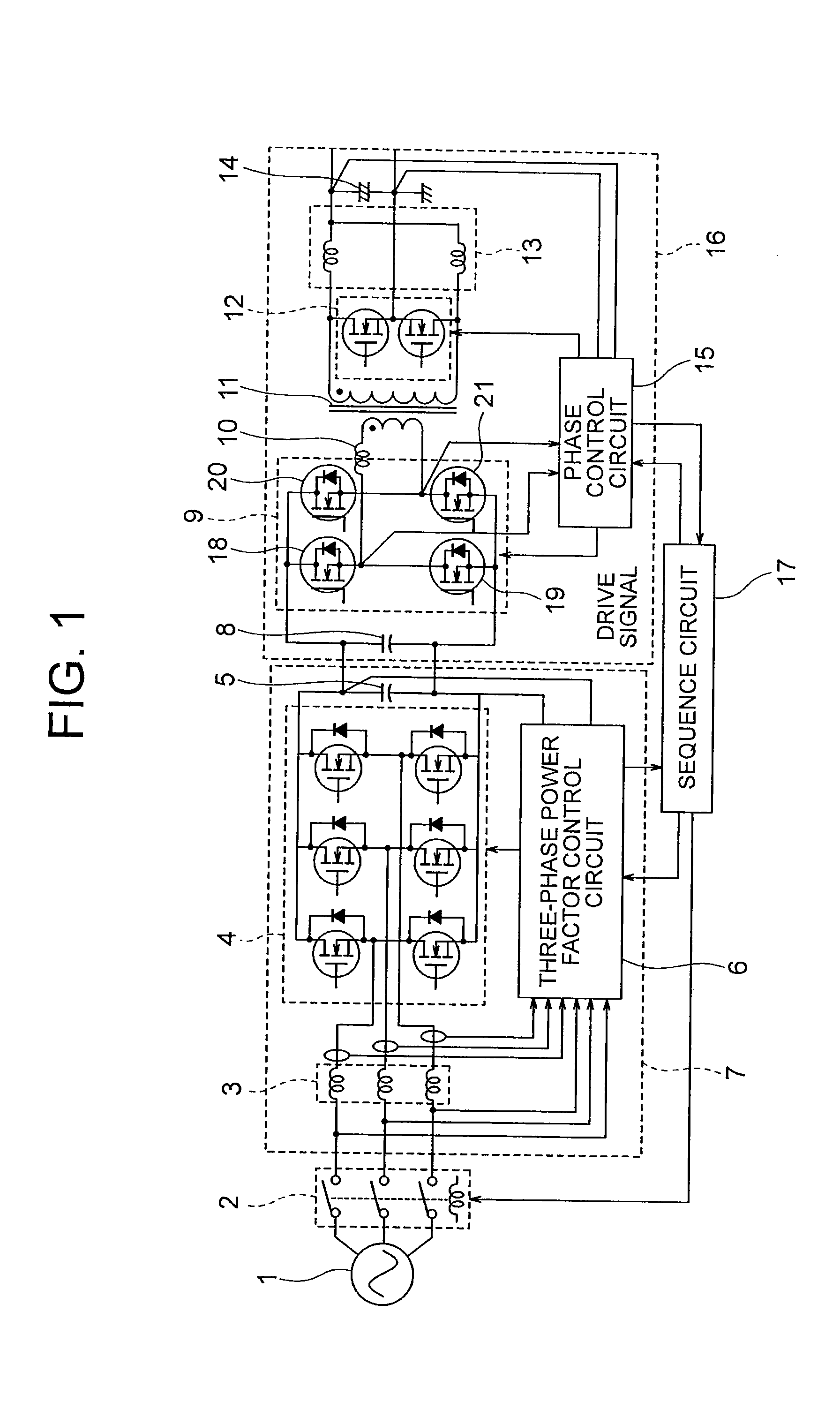
The present invention provides a DC power supply device that includes a power factor improvement circuit, a DC / DC converter, a relay circuit, and a sequence circuit. The power factor improvement circuit converts the AC voltage from the AC power supply into a DC voltage with improved power factor. The DC / DC converter converts the DC voltage from the power factor improvement circuit into a low voltage DC power for supplying to the load. The relay circuit switches between on and off of the input from the AC power supply. The sequence circuit connects the power factor improvement circuit, the DC / DC converter, and the relay circuit and detects the operational state of the DC / DC converter and outputs a drive signal to operate the relay circuit and power factor improvement circuit at the same time point. This results in a simplified circuit structure, lower cost, and smaller size.

Problems solved by technology

However, in a power semiconductor element using silicon (hereinafter referred to as Si), reductions of on-resistance and saturation voltage are close to limitations technically, and hence higher efficiency of the DC / DC converter is also in a saturated state.
Therefore, as described in Patent Literature 1, for example, there is a problem in that it is necessary to consider a protection method such as disposing a protection element or a relay for preventing the short circuit.
Therefore, the circuit becomes complicated, and hence it is difficult to downsize the DC power supply device.

Method used


Image

  • DC power source device and power conversion method
  • DC power source device and power conversion method
  • DC power source device and power conversion method

Examples


embodiment 1

[0024]A DC power supply device and a power conversion method according to Embodiment 1 of the present invention are described below in detail with reference to the drawings. Note that, this embodiment does not limit the present invention.

[0025]The present invention relates to a DC power supply device and a power conversion method for converting an AC power supply into a DC power supply. In particular, the present invention relates to a small loss and high efficiency DC power supply device and power conversion method, in which a DC / DC converter using a wide-bandgap semiconductor made of GaN or SiC as a switching element is used so as to achieve smaller size and lower cost of the circuit. The DC power supply device and the power conversion method according to the present invention are suitable particularly as a DC power supply device and a power conversion method used in a power supply system for a car, a ship, or an airplane.

[0026]FIG. 1 is a block diagram illustrating a structure of...


PUM


Abstract

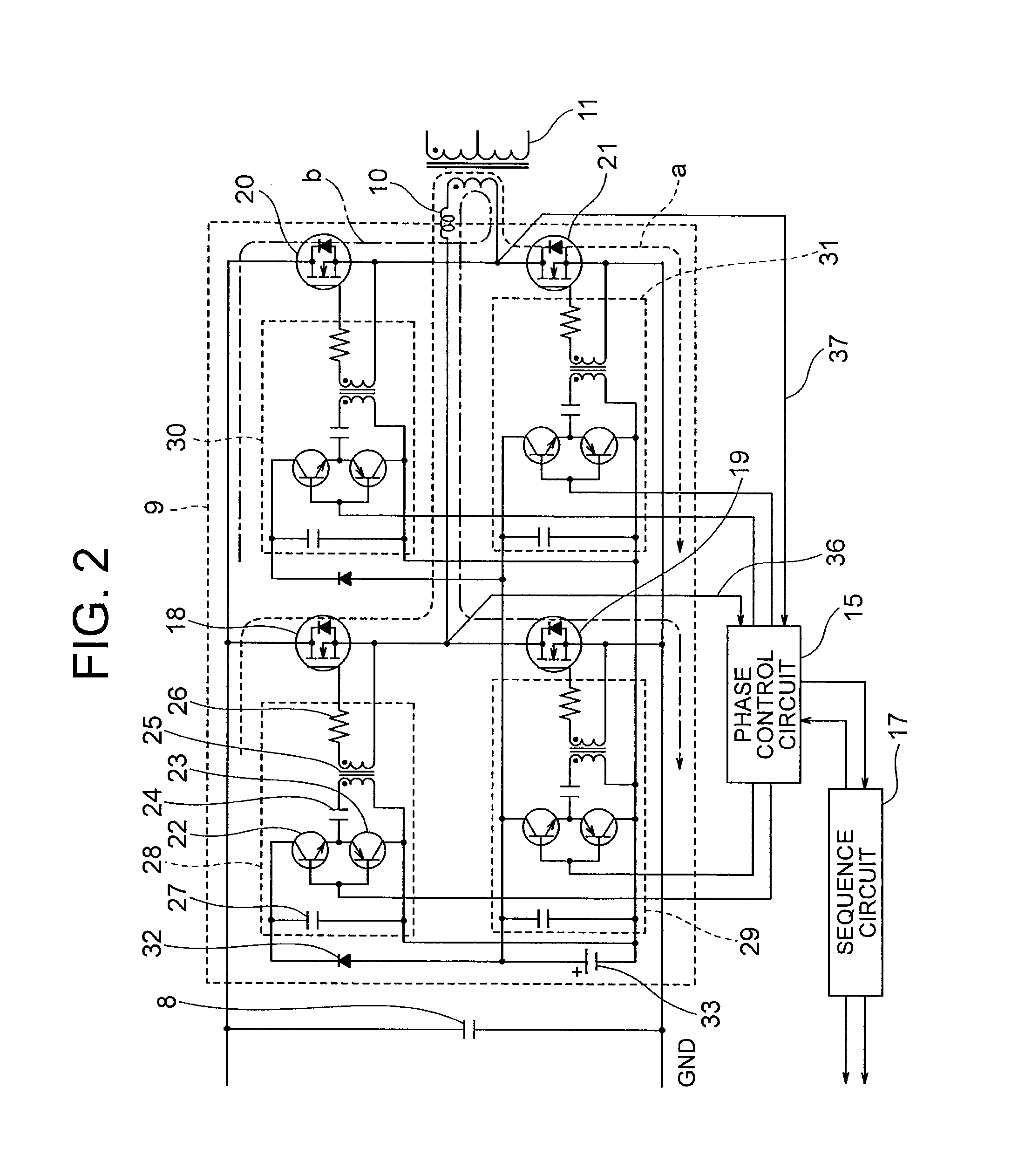
FETs disposed in a DC / DC converter are each driven by a drive transformer. A voltage from a single drive power supply disposed in common for the FETs is divided into positive and negative biases to be applied to the FETs, and an operational state of the FETs is detected based on voltage signals. A sequence circuit turns on an input from a three-phase AC power supply by driving a relay circuit at a time point when it is confirmed that the FETs have normally started stable ON / OFF operation, and drives a power factor improvement circuit, which converts AC voltage from the three-phase AC power supply into a DC voltage by simultaneously performing full-wave rectification and power factor improvement.

Description

TECHNICAL FIELD[0001]The present invention relates to a DC power source device (hereinafter referred to as a DC power supply device) and a power conversion method. In particular, the present invention relates to a DC power supply device and a power conversion method for converting an AC power supply into a DC power supply.BACKGROUND ART[0002]As an application field of the DC power supply device, which is supplied with AC power as an input, there is a power supply system for a ship or an airplane, for example. This type of a power supply system uses a three-phase generator as a primary power supply, which is supplied with three-phase AC power as an input so as to output a relatively high AC voltage such as AC 200 to 440 Vrms. In order to prevent harmonic ripple current generated when the primary power supply is full-wave rectified from badly affecting the primary power supply or other devices sharing the primary power supply, it is required to provide a DC power supply device capable...

Claims


Application Information

Patent Timeline
Patent Type & Authority Applications(United States)
IPC IPC(8): H02M3/335H02M7/219H02M1/00
CPCH02M7/219H02M3/33576H02M1/36H02M1/4216H02M3/33592G05F1/70Y02B70/10H02M1/007H02M1/4241H02M1/4258H02M1/4208H02M1/0054
Inventor SUZUKI, YASUJI
Owner MITSUBISHI ELECTRIC CORP
Learn More