
Gear shift control system for automatic transmission

Active Publication Date: 2014-03-06
SUZUKI MOTOR CO LTD
View PDF8 Cites 19 Cited by
  • Summary
  • Abstract
  • Description
  • Claims
  • Application Information

AI Technical Summary

Benefits of technology

The invention provides a gear shift control system for vehicles that can automatically detect when the vehicle is decelerating, such as during braking or when the driver releases the accelerator pedal. The system prevents the automatic transmission from upshifting during this deceleration, which ensures a comfortable ride and maneuverability of the vehicle. The system can also use different modes to determine the deceleration based on the depression of the brake pedal, the release of the accelerator pedal, the use of engine braking, and the regenerative braking force produced by the electric motor or generator. Additionally, the system can change the permissible gear shift range of the automatic transmission based on the degree of deceleration of the vehicle to enhance the quality of the gear shift inhibition control and efficiency in application of the braking force.

Problems solved by technology

This causes the speed reduction locus DT to intersect with the upshift gear shift lines US several times. The automatic transmission, thus, upshifts several times in a gear shift control mode even though the speed of the vehicle is not very high, which results in an increased possibility that the speed of the internal combustion engine falls in an engine stall range.
This results in sequential application of sudden engine braking to the vehicle, which will give occupants of the vehicle an uncomfortable ride and also lead to a bad maneuverability of the vehicle.
This may cause the automatic transmission to upshift or downshift undesirably depending upon the relation between the speed of the vehicle and the position of the accelerator pedal, which may result in a lack of braking force when the vehicle has started decelerating suddenly during acceleration.

Method used


Image

  • Gear shift control system for automatic transmission
  • Gear shift control system for automatic transmission
  • Gear shift control system for automatic transmission

Examples


first embodiment

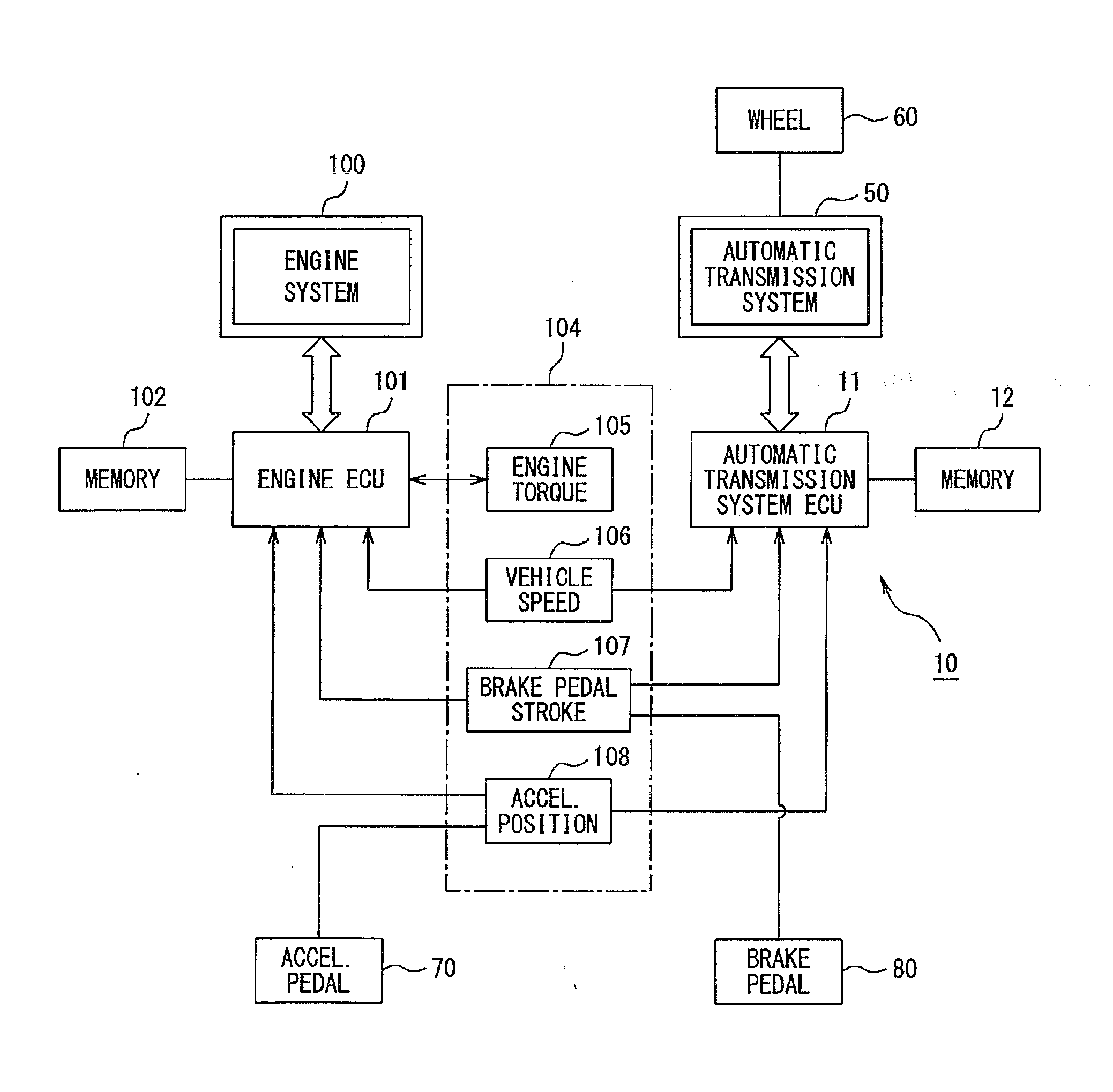
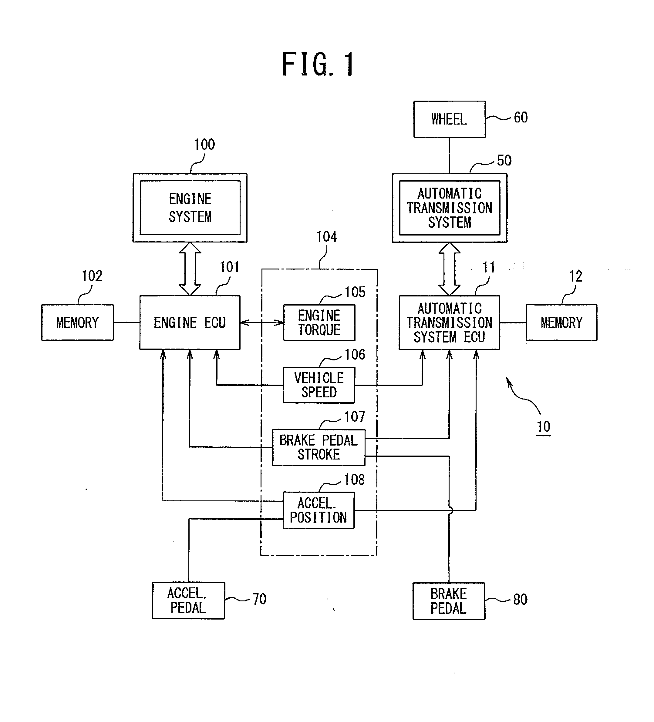
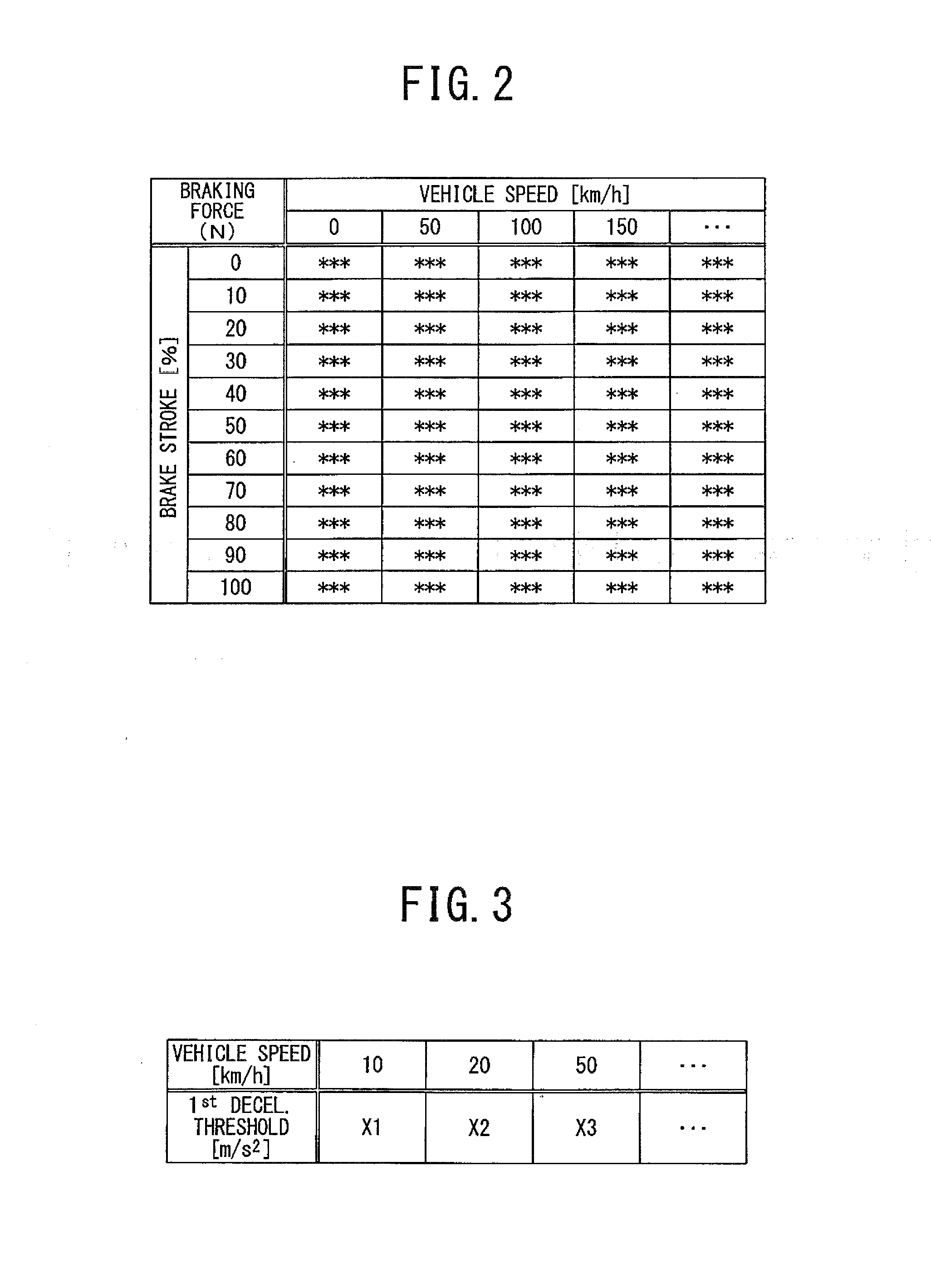
[0041]Embodiments will be described below with reference to the drawings. FIGS. 1 to 7 illustrate a gear shift control system 10 for an automatic transmission according to the

[0042]The gear shift control system 10 is designed to control an operation of the automatic transmission which is mounted on an automotive vehicle along with an internal combustion engine. The automatic transmission works to automatically change the speed of a drive shaft of the internal combustion engine and transmit the torque of the drive shaft to a drive axle of road wheels 60 to run the vehicle.

[0043]The internal combustion engine, as referred to herein, is engineered to burn a mixture of air and fuel sprayed into combustion chambers to reciprocate pistons, thereby rotating the drive shaft through a crankshaft to output the torque. An engine system 100 which includes the internal combustion engine and components or actuators such as fuel injectors is generally controlled in operation by an engine ECU (Elec...

third embodiment

[0075]FIGS. 9 and 10 illustrate an example of a vehicle in which the gear shift control system 10 of the third embodiment is mounted.

[0076]In FIG. 9, the automatic transmission ECU 11 of the gear shift control system 10 includes the vehicle speed determiner 106, the brake pedal stroke determiner 107, and the accelerator position determiner 108 which are shared with the engine ECU 101 and also includes the engine torque determiner 105 to select one of the gear ratios of the automatic transmission based on running conditions of the vehicle. Specifically, the gear shift control system 10 is equipped with the automatic transmission ECU 11, the memory 12, the engine torque determiner 105, the vehicle speed determiner 106, the brake pedal stroke determiner 107, and the accelerator position determiner 108.

[0077]The automatic transmission ECU 11 of the gear shift control system 10 executes a gear shift control program, as shown in a flowchart of FIG. 10. The same step numbers as employed in...

fourth embodiment

[0083]FIGS. 11 to 13 illustrates the gear shift control system 10 according to the

[0084]In FIG. 11, the gear shift control system 10 is mounted in a hybrid electric vehicle (HEV) equipped with a combination of a gasoline-powered internal combustion engine (i.e., the engine system 100) and an electric motor 200 driven by electric power stored in a storage battery 90 which are used as a drive source to produce torque to rotate wheels 60 of the vehicle. The storage battery 90 of the vehicle can be recharged by an external power supply. The electric motor 200 may be engineered as an electric generator to produce electric energy. Alternatively, a separate electric generator may be installed in the vehicle. The electric generator (i.e., the electric motor 200 or the separate electric generator), which will also be referred as a generator motor 200 below, is driven in a regenerative braking mode during running or decelerating of the vehicle to produce the regenerative electric energy for u...


PUM


Abstract

A gear shift control system for vehicles is provided which mathematically calculates a rate of deceleration of the vehicle equipped an automatic transmission upon start of deceleration of the vehicle and inhibits the automatic transmission from upshifting or changes a permissible gear shift range of the automatic transmission as a function of the rate of deceleration of the vehicle, thereby ensuring a desired degree of braking force including an engine braking force while the vehicle is decelerating.

Description

CROSS REFERENCE TO RELATED DOCUMENT[0001]The present application claims the benefit of priority of Japanese Patent Application No. 2012-196314 filed on Sep. 6, 2012, the disclosure of which is totally incorporated herein by reference.BACKGROUND OF THE INVENTION[0002]1. Technical Field of the Invention[0003]The present invention relates generally to a gear shift control system for an automatic transmission for vehicles, and more particularly to such a control system designed to control an operation of the automatic transmission when it is required to decelerate the vehicle.[0004]2. Background Art[0005]Usually, an internal combustion engine in automotive vehicles is rotated in a selected one of multiple gear ranges in order to drive road wheels of the vehicle at a desired torque. Specifically, the vehicle has an automatic transmission disposed between a drive shaft and the wheels to provide a given torque to the wheels either in a low-speed range or in a high-speed range[0006]Typical ...

Claims


Application Information

Patent Timeline
IPC IPC(8): B60W20/00B60W10/18B60W10/11
CPCB60W20/30Y10S903/947B60W10/18B60W10/11B60W30/18072B60W2720/106F16H61/0213F16H61/16F16H61/21F16H2061/0237F16H2061/163
Inventor KAWAMOTO, SHUHEIYOSHIDA, SATOHIRO
Owner SUZUKI MOTOR CO LTD
Learn More