Ankle-foot orthotic

an ankle and foot technology, applied in the field of orthotics, can solve the problems of reducing the comfort of patients, and creating substantial shock, or force, in the heel, etc., and achieves the effects of reducing the risk of injury, being easy to use, and being inexpensive to manufactur

Inactive Publication Date: 2014-03-06
DRILLIO ROBERT C
View PDF5 Cites 23 Cited by
  • Summary
  • Abstract
  • Description
  • Claims
  • Application Information

AI Technical Summary

Benefits of technology

[0011]It is yet another object of the present invention to provide an orthotic device as described above that enables the treated ankle and foot to closely simulate the natural movement of a lower extremity throughout a proper walking gait cycle.
[0012]It is yet still another object of the present invention to provide an orthotic device as described above that is specifically designed to allow for attenuation of the initial heel strike force (i.e., to simulate the proper absorption of force onto the heel over an extended period of time to minimize the risk of injury).
[0013]It is even still another object of the present invention to provide an orthotic device as described above that is designed to allow for adequate deceleration, or rocking, of the foot from initial heel strike to throughout the stance phase as weight transfers from the treated extremity to the other extremity.
[0014]It is another object of the present invention to provide an orthotic device as described above that includes a limited number of parts, that is inexpensive to manufacture and that is easy to use. Accordingly, as a principal feature of the present invention, there is provided an orthotic for treating a lower extremity of a patient, the lower extremity comprising a tibial portion, an ankle portion, a heel portion and a foot portion, the orthotic comprising (a) an upper support member adapted to conform to the tibial portion, (b) a lower support member adapted to conform to the foot, heel and ankle of the patient, the lower support member being pivotally coupled to the upper support member, (c) wherein the lower support member comprises a rigid cup for receiving the heel and ankle portions of the lower extremity, the cup being shaped to define a slot that enables the cup to compress upon the application of a suitable compressive force thereto.

Problems solved by technology

Although useful in providing the patient with the requisite degree of stabilization for adequate weight support, ankle-foot orthotics that rely on a unitary, solid design inherently lack the flexibility to assist the patient to closely simulate the proper gait cycle.
In particular, it has been found that the heel strike is a traumatic event that creates substantial amount of shock, or force, in the heel.
However, traditional AFOs that rely upon a solid design fail, among other things, to properly decelerate the heel upon initial heel strike to create a smooth roll and thereby simulate proper movement of the heel rocker.
Rather, solid ankle design AFOs tend to throw the weight of the patient forward and / or outward in a rapid manner and without proper control, which is highly undesirable.

Method used


Image

  • Ankle-foot orthotic
  • Ankle-foot orthotic
  • Ankle-foot orthotic

Examples


first embodiment

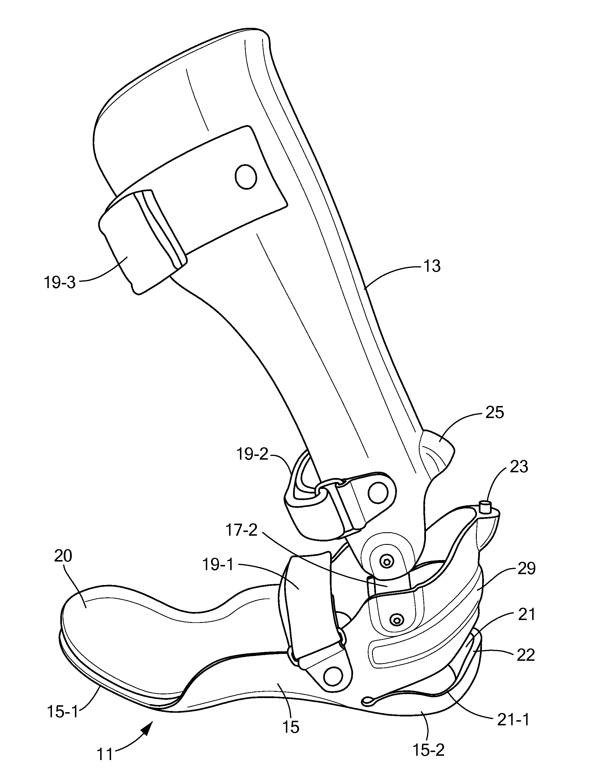
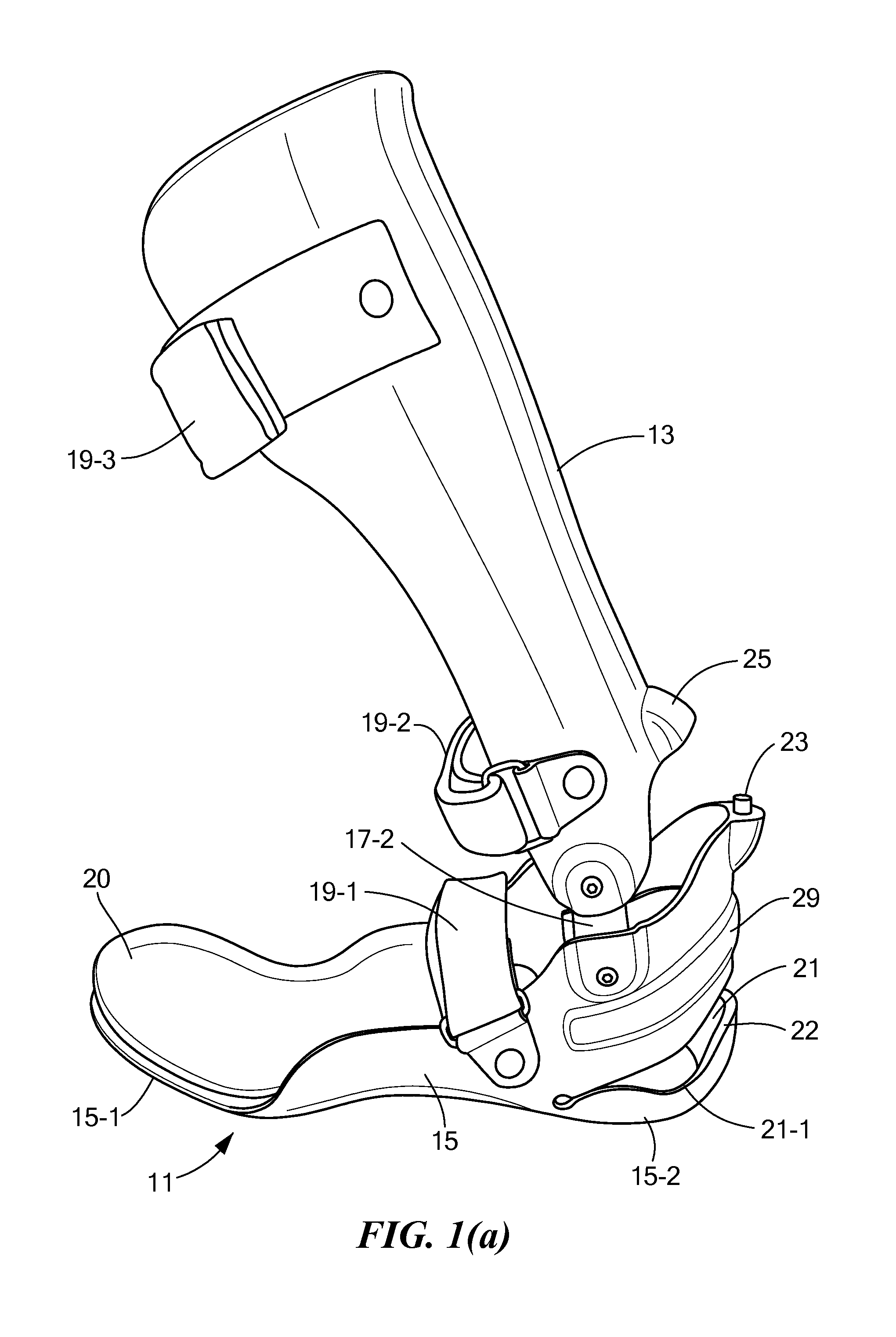
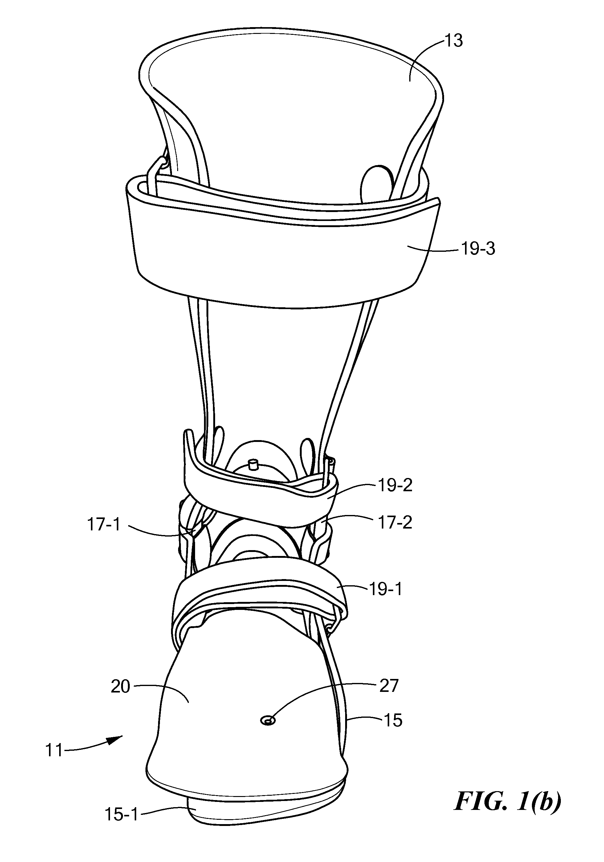
[0022]Referring now to the figures, there is a shown an ankle-foot orthotic device that is constructed according to the teachings of the present invention, the orthotic device being identified generally by reference numeral 11. As will be described in detail below, orthotic device 11 is specifically designed to influence the rockers of the foot of a patient in order to induce a relatively smooth gait and a near normal stride length, which are principal objects of the present invention.

[0023]As seen most clearly in FIGS. 1(a)-2(b), orthotic device, or orthotic, 11 comprises an upper support member 13 that is designed to conform to the posterior aspect of the tibia of a patient, a lower support member 15 that is designed to conform to a portion of the foot and ankle of the patient, a pair of opposing dorsiflexion assist members 17 that pivotally join together members 13 and 15, a plurality of straps 19 for retaining upper and lower support members 13 and 15 onto the lower extremity of...

second embodiment

[0040]For instance, referring now to FIGS. 4(a), there is shown an ankle-foot orthotic device that is constructed according to the teachings of the present invention, the orthotic device being identified generally by reference numeral 111. As can be seen device 111 is similar to device 11 in that device 111 comprises an upper support member 113 that is designed to conform to the posterior aspect of the tibia of a patient, a lower support member 115 that is designed to conform to a portion of the foot and ankle of the patient, a pair of opposing dorsiflexion assist members 117 that pivotally join together members 113 and 115, a plurality of straps 119 for retaining upper and lower support members 113 and 115 onto the lower extremity of the patient, and a removable foot overlay 120 that is mounted onto lower support member 115 to promote proper pronation into midstance.

[0041]Device 111 differs slightly from device 11 in a few notable ways. As a first distinction, device 111 includes a...


PUM


Abstract

An ankle-foot orthotic device is designed to closely simulate the natural movement of a lower extremity throughout a proper walking gait cycle. The orthotic device includes upper and lower support members that are pivotally coupled by opposing dorsiflexion assist members. The lower support member includes a rigid, unitary cup for receiving the heel and ankle portions of the lower extremity. The cup is shaped to include a continuous slot that allows for at least 5 degrees of compression upon initial heel strike and thereby promotes a smooth, decelerating heel roll. The lower support member additionally includes a rigid footplate on which is mounted a flexible overlay, the overlay extending beyond the footplate in the medial aspect to promote proper pronation into midstance. A compressible stop is mounted on the lower support member and selectively contacts the upper support member to prevent hyperextension of the lower extremity.

Description

FIELD OF THE INVENTION[0001]The present invention relates generally to orthotic devices and more particularly to orthotics for the ankle and foot.BACKGROUND OF THE INVENTION[0002]An ankle-foot orthosis (also commonly referred to in the art simply as an AFO) is an orthotic device that firmly surrounds at least a portion of the ankle and foot of a patient. An ankle-foot orthosis is commonly constructed as a relatively lightweight and rigid brace that supports the lower leg and foot of a patient and serves to, among other things, properly control the position and motion of the ankle and foot of the patient through each gait cycle, compensate for muscular weakness and / or correct deformities. For this reason, ankle-foot orthotic devices are commonly utilized in the treatment of patients suffering from a wide variety of muscular disorders, such as stroke patients.[0003]One type of ankle-foot orthosis which is well known in the art is constructed as a rigid brace which utilizes a solid ank...

Claims


Application Information

Patent Timeline
Patent Type & Authority Applications(United States)
IPC IPC(8): A61F5/01
CPCA61F5/0127
Inventor DRILLIO, ROBERT C.
Owner DRILLIO ROBERT C
Why Eureka
Try Eureka