Medical instrument

Active Publication Date: 2014-03-06
COLUMBIA PEAK VENTURES LLC
View PDF1 Cites 2 Cited by
  • Summary
  • Abstract
  • Description
  • Claims
  • Application Information

AI Technical Summary

Benefits of technology

The patent text describes a design for a liquid ejecting apparatus that reduces ringing in the output voltage of a switching circuit. By mounting the first transistor, second transistor, and capacitor on the first wiring layer side of a multilayer wiring board and forming an electrical loop through the fifth wiring in the second wiring layer, the area of the electrical loop is reduced, which helps to suppress an increase in parasitic inductance and ringing of the output voltage. This design also allows for easier mounting of the components and improved stability of the switching circuit, making it suitable for use in medical instruments.

Problems solved by technology

When an analog drive waveform signal is power-amplified in an analog form to directly generate an analog drive signal, significant power loss occurs and power efficiency is degraded.
In an ink jet printer, the occurrence of ringing leads to the occurrence of EMI noise.
As a result, the amount of ink to be ejected varies, thereby causing interference with improvement in printing quality.
In a medical instrument using a fluid transport apparatus or a fluid ejecting apparatus, the occurrence of ringing leads to the occurrence of EMI noise, causing interference with the operation of the apparatus itself or peripherals.
For example, in a medical instrument using a fluid ejecting apparatus, the occurrence of EMI noise with ringing causes variation in the amount of fluid to be ejected.
For this reason, there is a limitation to suppress ringing, that is, to improve printing quality or to stably transport a fluid.

Method used


Image

  • Medical instrument
  • Medical instrument
  • Medical instrument

Examples


Embodiment Construction

[0064]Hereinafter, a preferred embodiment of the invention will be described in detail referring to the drawings. The drawings to be used are for convenience of description. The following embodiment is not intended to unduly limit the content of the invention described in the appended claims. It is not always true that the entire configuration described below is the essential constituent requirement of the invention.

[0065]Hereinafter, an embodiment of the invention will be described in the following sequence.

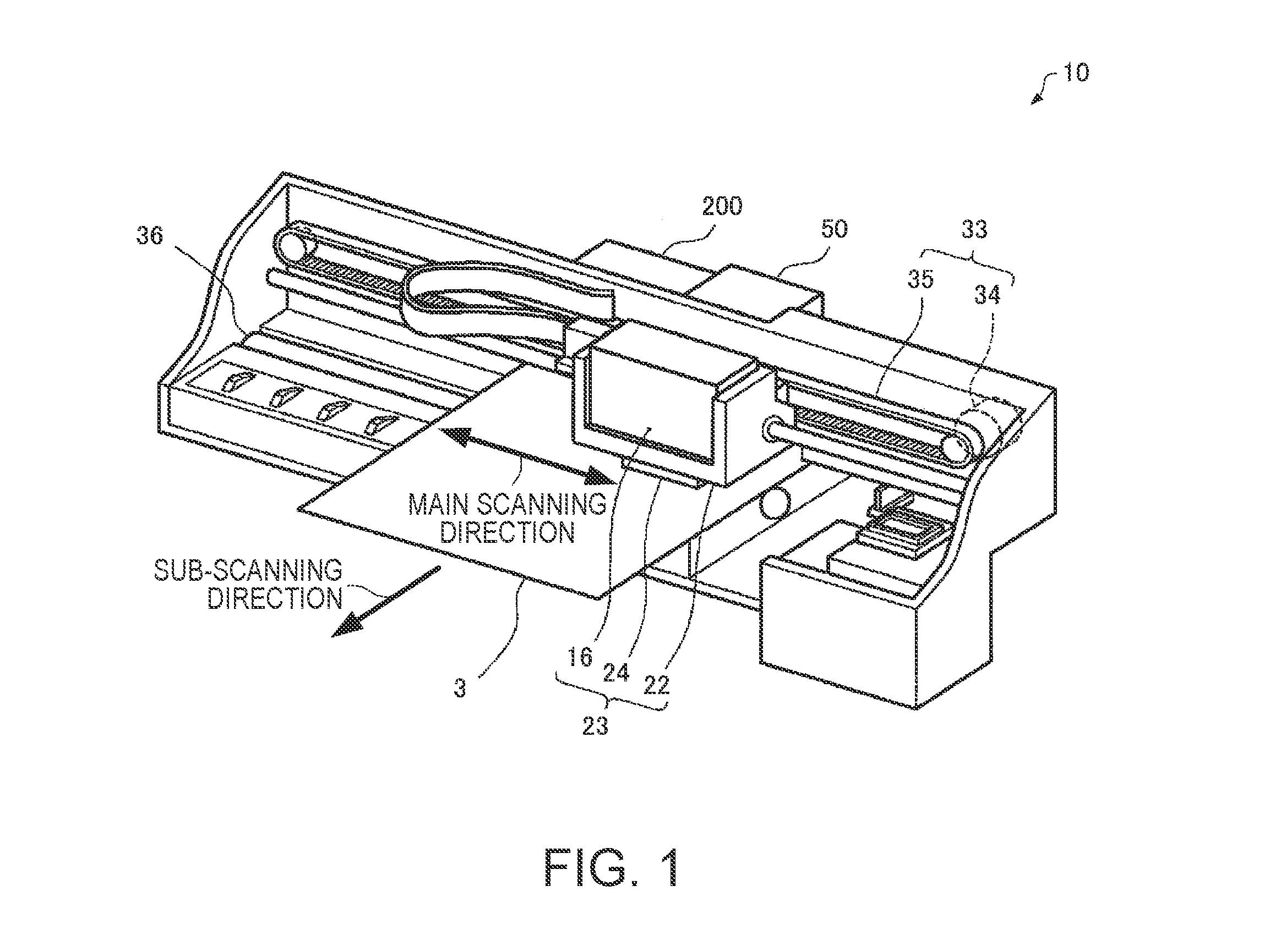
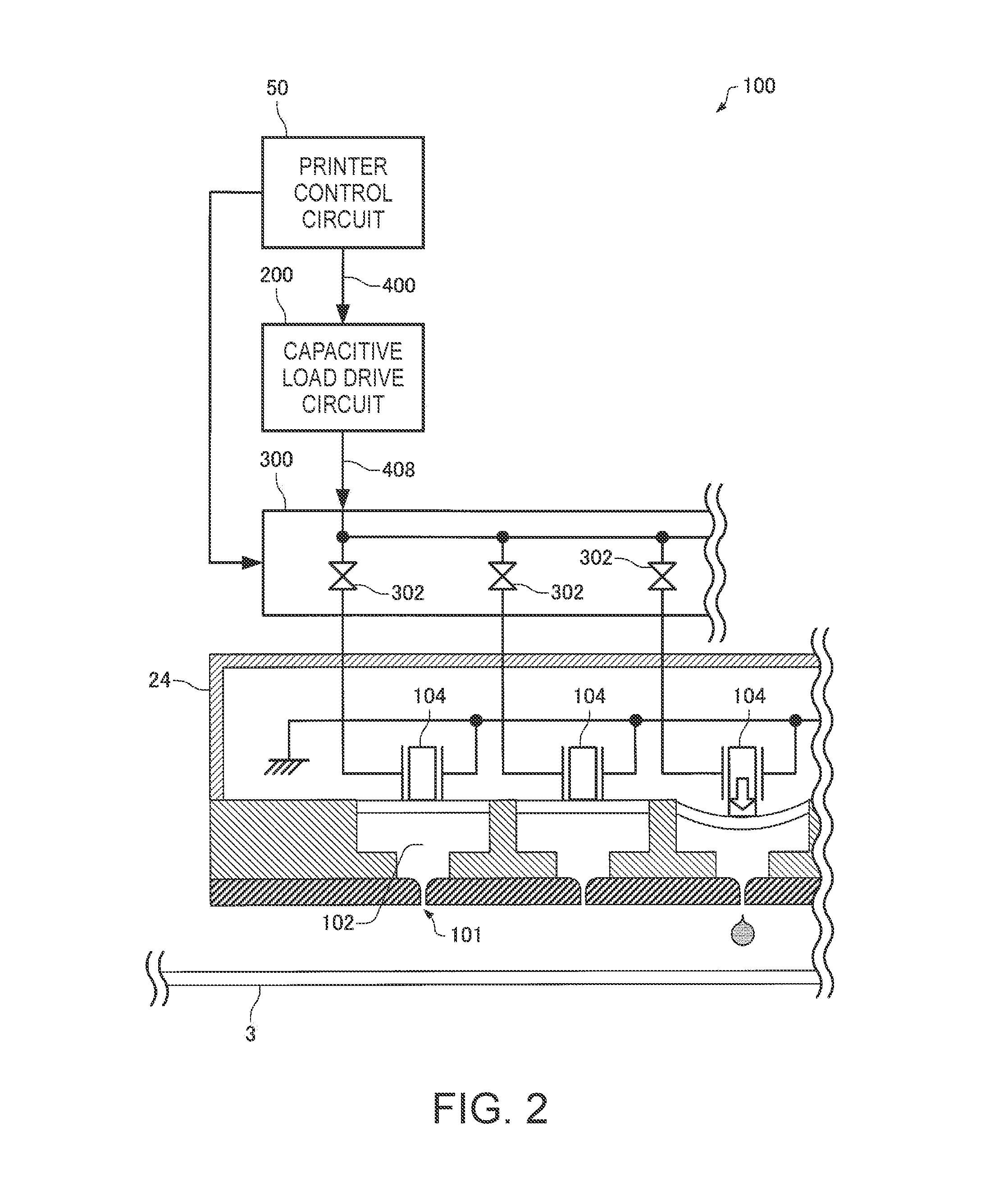
[0066]1. Configuration example of printing apparatus and liquid ejecting apparatus

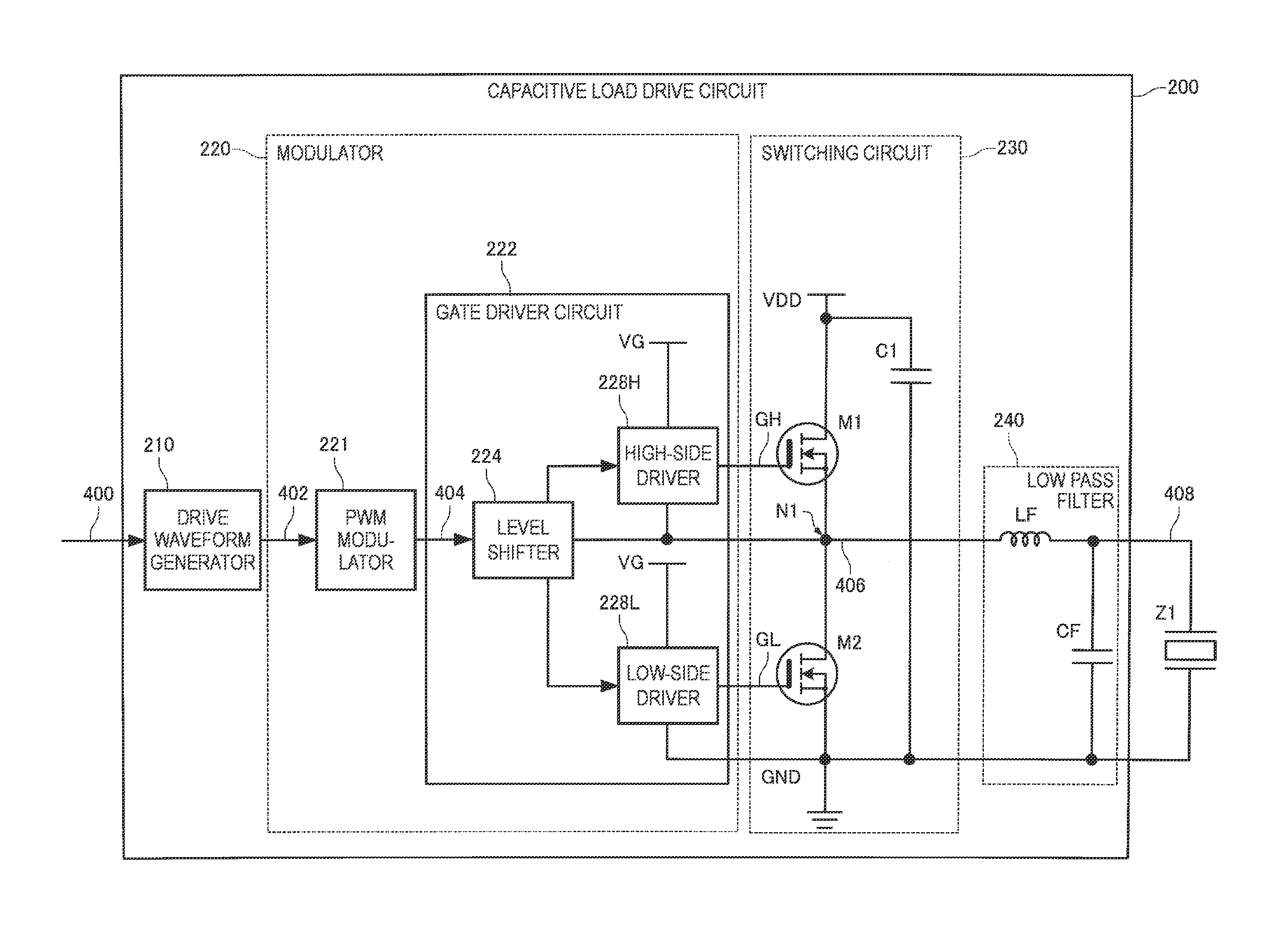
[0067]2. Circuit configuration of capacitive load drive circuit

[0068]3. Arrangement example of switching circuit

[0069]4. First modification of arrangement example of switching circuit

[0070]5. Second modification of arrangement example of switching circuit

[0071]6. Third modification of arrangement example of switching circuit

[0072]7. Fourth modification of arrangement example of switching circuit

[00...


PUM


Abstract

A medical instrument includes a multilayer wiring board having first, second and third wirings, a fourth wiring formed in a first wiring layer, and a fifth wiring formed in a second wiring layer. A first via conductor electrically connects the third and fifth wirings. A second via conductor electrically connects the fourth and fifth wirings. The medical instrument further includes first and second transistors, a second transistor, and a capacitor mounted on the first wiring layer side of the multilayer wiring board. The drain and source electrodes of the first transistor are electrically connected to the first and second wirings, respectively. The drain electrode of the second transistor is electrically connected to the second wiring. The source electrode of the second transistor is electrically connected to the third wiring. The first and second electrodes of the capacitor are electrically connected to the first and fourth wirings, respectively.

Description

[0001]This application claims priority to Japanese Patent Application Nos. 2012-196552 filed on Sep. 6, 2012 and Japanese Patent Application No. 2012-232219 filed on Oct. 19, 2012. The entire disclosure of Japanese Patent Application Nos. 2012-196552 and 2012-232219 is hereby incorporated herein by reference.BACKGROUND[0002]1. Technical Field[0003]The present invention relates to a semiconductor device, a medical instrument, and the like.[0004]2. Related Art[0005]Similar to an ejecting head which is mounted in an ink jet printer, there are many actuators constituted by a capacitive load, such as a piezoelectric element. In order to drive an actuator as a capacitive load, a drive signal having a certain level of power is required. Accordingly, a drive waveform signal as a source of a drive signal is power-amplified to generate a drive signal. When an analog drive waveform signal is power-amplified in an analog form to directly generate an analog drive signal, significant power loss o...

Claims


Application Information

Patent Timeline
IPC IPC(8): A61M5/172H01L27/06
CPCH01L27/0629A61M5/172A61M5/14232
Inventor OSHIMA, ATSUSHIIDE, NORITAKA
Owner COLUMBIA PEAK VENTURES LLC
Why Eureka
Try Eureka