Energy efficient cooling and heating system

a technology of energy-efficient cooling and heating system, applied in the direction of heat pump, heating and refrigeration combination, refrigerating machine, etc., can solve the problem that the cost of providing the required cooling and heating capacity can be high for convenience stores, and achieve the effect of improving the efficiency of the heat pump

Active Publication Date: 2014-03-13
HEARTSWORK LLC
View PDF10 Cites 10 Cited by
  • Summary
  • Abstract
  • Description
  • Claims
  • Application Information

AI Technical Summary

Benefits of technology

[0005]A cooling and heating system with a first heat exchange loop and a second heat exchange loop. The first heat exchange loop uses a first heat transfer fluid that is passed through a compression / evaporation refrigeration cycle to cool a refrigerated space and to collect waste heat, and then pumps that heat transfer fluid to a remote heat pump in the winter where the waste heat is used to improve the efficiency of the heat pump. The first heat exchange loop may also pump the first heat transfer fluid to a remote water heater where the waste heat is used to heat water. The heat transfer fluid is then passed through an underground earth loop portion where it is cooled to about 55°. The second heat exchange loop uses a second heat transfer fluid to cool the heat pump in the summer, and also includes a second underground earth loop. The first underground earth loop portion and the second underground earth loop portion may be interconnected so that a single heat transfer fluid flows through both heat exchange loops.

Problems solved by technology

Providing the required cooling and heating capacity can be expensive for convenience stores, or for any facility requiring both cooling and heating.

Method used


Image

  • Energy efficient cooling and heating system
  • Energy efficient cooling and heating system
  • Energy efficient cooling and heating system

Examples


Embodiment Construction

[0020]For the purposes of promoting an understanding of the principles of the invention, reference will now be made to certain preferred embodiments and specific language will be used to describe the same. It will nevertheless be understood that no limitation of the scope of the invention is thereby intended, such alterations and further modifications in the illustrated device, and such further applications of the principles of the invention as illustrated therein being contemplated as would normally occur to one skilled in the art to which the invention relates.

[0021]1. Geothermal Earth Loop System.

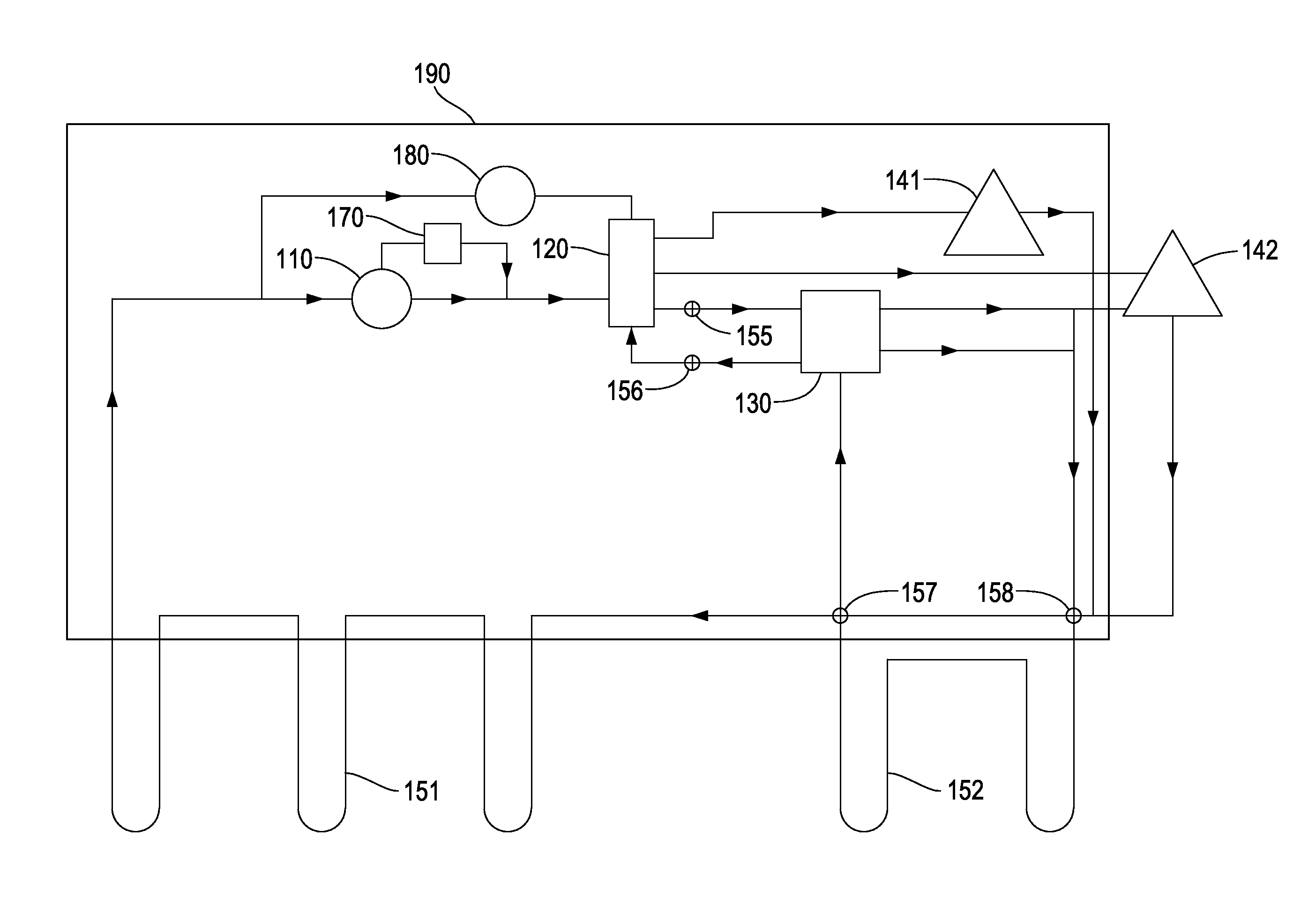
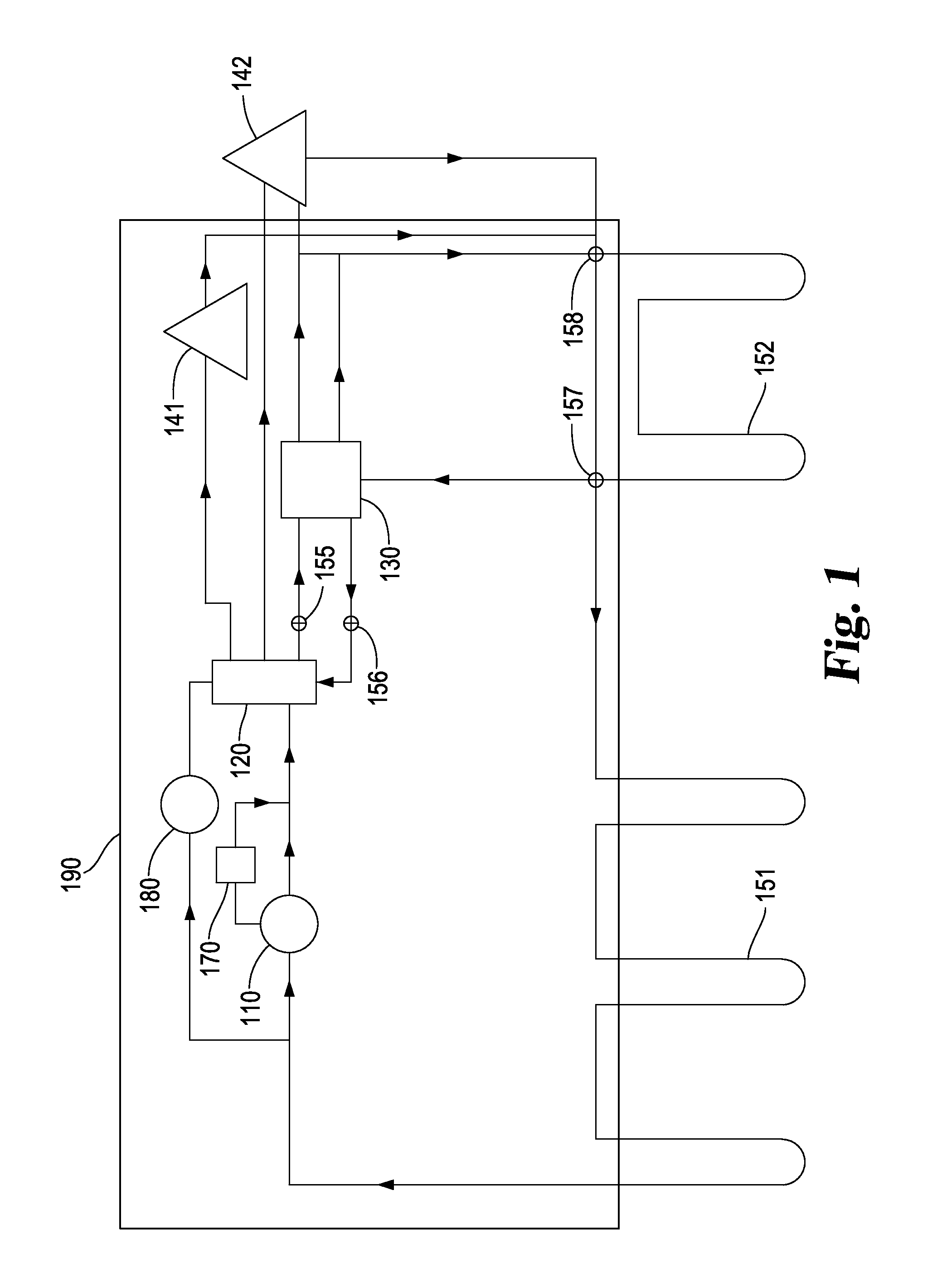
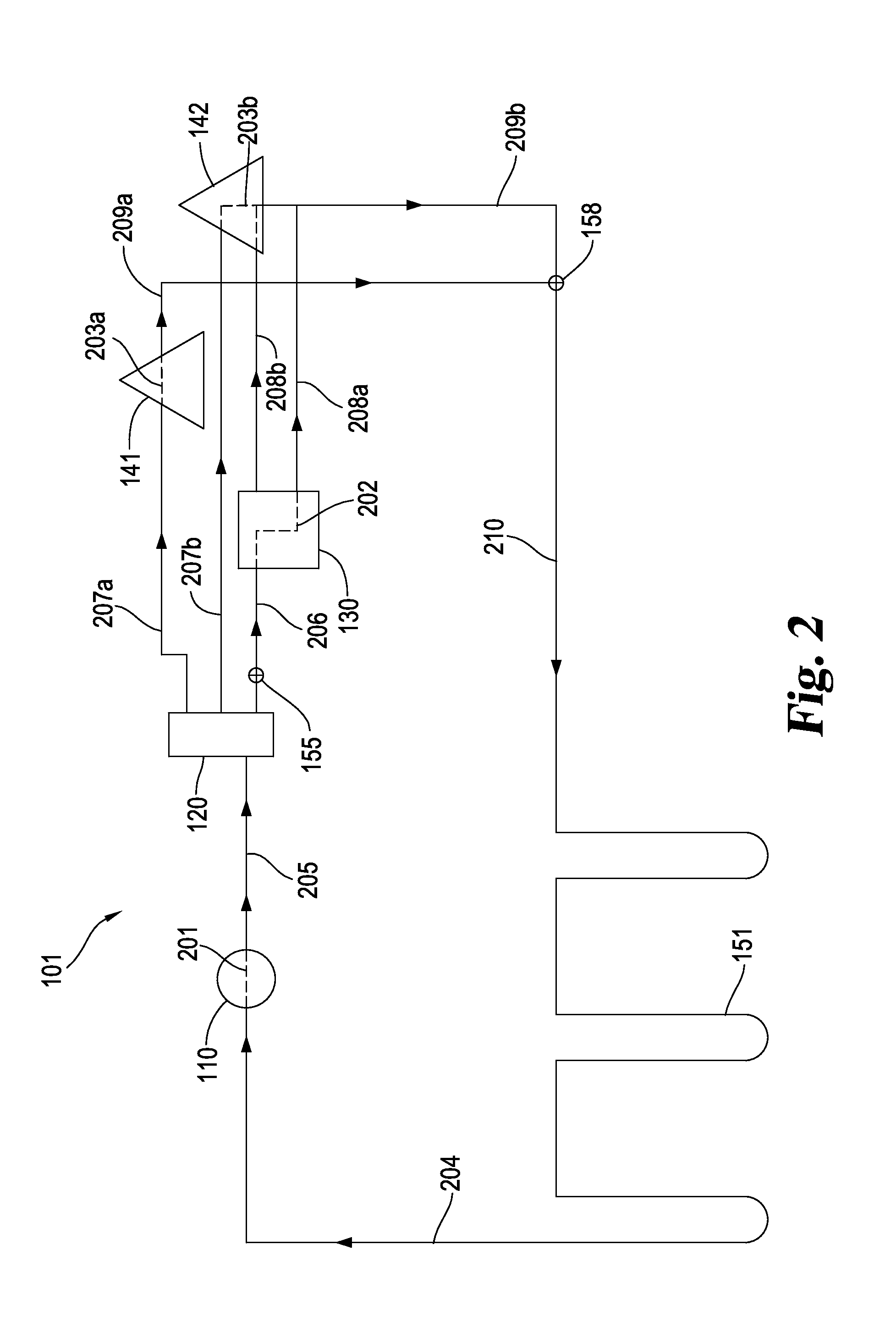
[0022]In one aspect of the present invention there is provided a cooling and heating system, comprising a first heat exchange loop and a second heat exchange loop. A first heat transfer fluid flows through the first heat exchange loop and a second heat transfer fluid flows through the second heat exchange loop. The first heat exchange loop includes a first underground earth loop portion ...


PUM


Abstract

A cooling and heating system with a first heat exchange loop and a second heat exchange loop. The first heat exchange loop uses a first heat transfer fluid that is passed through a compression/evaporation refrigeration cycle to cool a refrigerated space and to collect waste heat, and then pumps that heat transfer fluid to a remote heat pump in the winter where the waste heat is used to provide warm air. The first heat exchange system may also pump some or all of the first heat transfer fluid to a remote water heater where the waste heat is used to heat water. The heat transfer fluid is then passed through an underground portion where it is cooled to about 55°. The second heat exchange loop uses a second heat transfer fluid to cool the heat pump in the summer, and may pump that second heat transfer fluid to a remote water heater where waste heat is used to heat water. The first earth loop and the second earth loop may be interconnected so that a single heat transfer fluid is used in both loops, or they may be operated so that the heat transfer fluid flowing in the first loop is isolated from the heat transfer fluid flowing through the second loop.

Description

CROSS-REFERENCE TO RELATED APPLICATIONS[0001]This application claims the benefit of U.S. Provisional Application No. 61 / 700,624, filed Sep. 13, 2012, which is hereby incorporated by reference in its entirety.BACKGROUND OF THE INVENTION[0002]Convenience stores typically require refrigeration and / or freezing capacity and a source of cool air when ambient temperatures are too warm. Convenience stores also frequently require a source of hot water for store use and / or for use in an associated car wash, laundromat, etc., and may require a source of warm air when ambient temperatures are too cool.[0003]Providing the required cooling and heating capacity can be expensive for convenience stores, or for any facility requiring both cooling and heating. While improvements have been made in energy-efficient cooling and heating, there are still gains and improvements to be made across the various technologies.[0004]A need exists for energy efficient cooling and heating, particularly for use in a ...

Claims


Application Information

Patent Timeline
Patent Type & Authority Applications(United States)
IPC IPC(8): F25B29/00
CPCF25B29/00F25B29/003F25B30/06
Inventor CROOK, DENNIS MAQ
Owner HEARTSWORK LLC
Why Eureka
Try Eureka