Controlled temperature cabinet system and method

a temperature control and cabinet technology, applied in the field of temperature control systems, can solve the problems of merely storing medical items, not being suited for use, and a risk of injury to patients, and achieve the effect of improving heat pump efficiency

Inactive Publication Date: 2006-09-19
MEDICAL PRODS
View PDF32 Cites 5 Cited by
  • Summary
  • Abstract
  • Description
  • Claims
  • Application Information

AI Technical Summary

Benefits of technology

[0011]The heat pumps typically include a pair of heat sinks surrounding a solid state thermoelectric device ;(i.e., a Peltier chip). The heat sinks are typically constructed of thermally conductive material and include fins to enable air to circulate and transfer thermal energy from the heat sinks to the surrounding environment. Further, fans are disposed adjacent each heat sink to circulate air and enhance heat pump efficiency. The thermoelectric device causes one heat sink to absorb thermal energy (i.e., thereby cooling the surrounding environment), while enabling the other heat sink to expel thermal energy (i.e., heat the surrounding environment) based on the direction of current or voltage polarity directed to the device. Since the heat pumps utilize a solid state thermoelectric device, the heat pumps have no moving parts, except for the fans, and are extremely reliable. The heat pumps are installed in the cabinet such that one heat sink is typically disposed exteriorly of the cabinet while the other heat sink is disposed within the cabinet interior.

Problems solved by technology

However, existing cabinets utilized in ambulance and other medical vehicles typically do not provide a temperature controlled environment, but rather merely store medical items.
Thus, drugs or I.V. solutions that are initially thermally treated to have temperatures within their appropriate utilization temperature range may quickly attain temperatures outside that range when stored in cabinets lacking temperature control capability, thereby risking injury to the patient.
Although temperature controlled cabinets may exist in other contexts, those cabinets typically require A.C. (i.e., alternating current) voltage to maintain the cabinet interior at a desired temperature and are not suited for use within ambulances or other medical vehicles since only D.C. (i.e., direct current) voltage is available in these vehicles.
Further, there is no provision for incorporating temperature control capability into cabinets previously disposed in ambulances and other medical vehicles.

Method used


Image

  • Controlled temperature cabinet system and method
  • Controlled temperature cabinet system and method
  • Controlled temperature cabinet system and method

Examples


Embodiment Construction

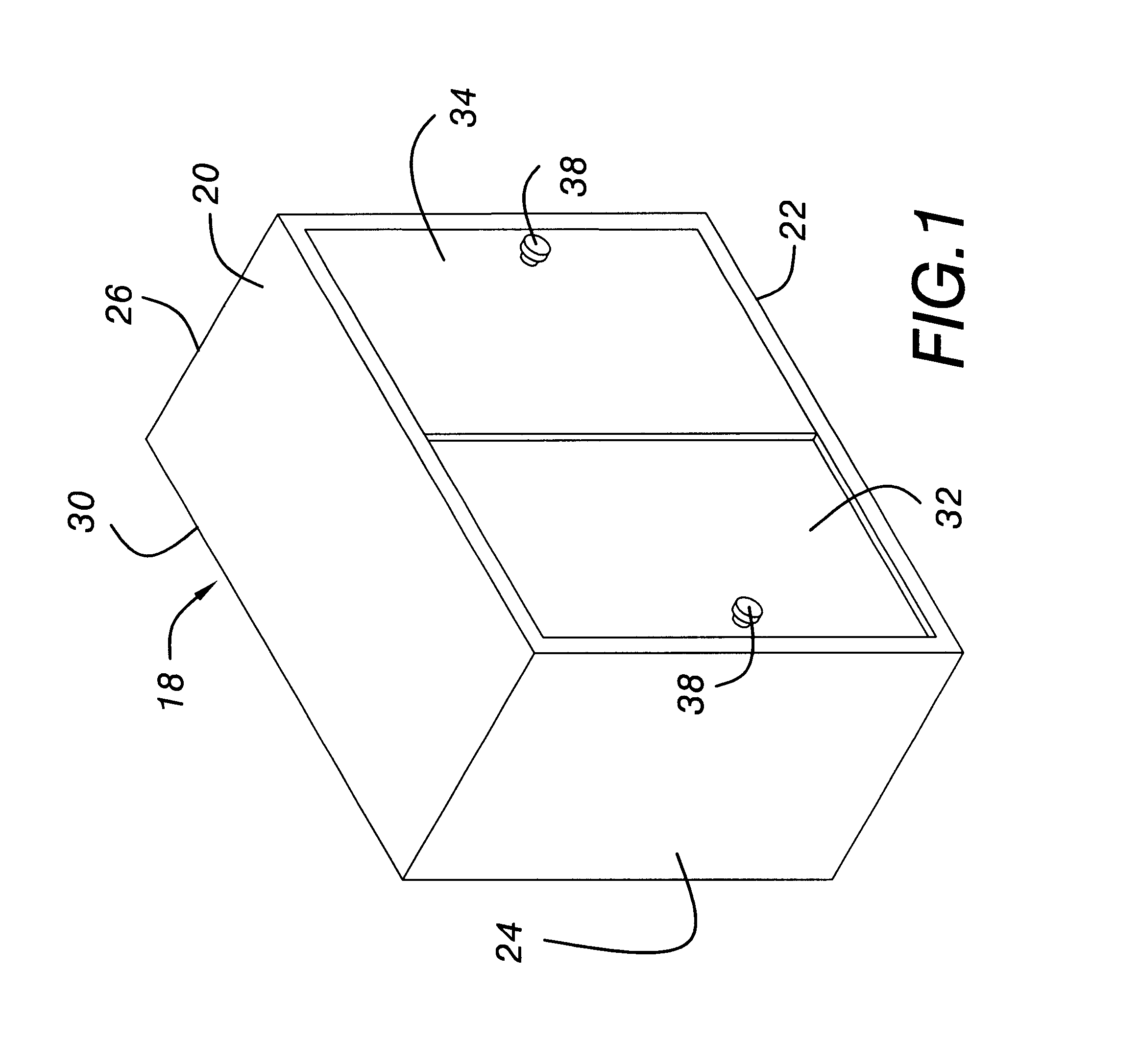
[0034]An exemplary cabinet of the type employed by the present invention for use in ambulance or other medical vehicles to contain medical items (e.g., drugs or intravenous solution contained with I.V. bags) is illustrated in FIG. 1. Specifically, cabinet 18, typically disposed along with a plurality of other cabinets within an ambulance or other medical vehicle interior, is similar in shape to a substantially rectangular box and includes top and bottom walls 20, 22 side walls 24, 26 and rear wall 30. The cabinet front typically includes doors 32, 34, preferably disposed between top and bottom walls 20, 22 and side walls 24, 26. Each wall is substantially rectangular wherein top and bottom walls 20, 22 include substantially similar dimensions, while side walls 24, 26 also include substantially similar dimensions. Rear wall 30 is disposed between top and bottom walls 20, 22 and side walls 24, 26 such that the cabinet walls and doors collectively define a cabinet interior. It is to be...


PUM


Abstract

A temperature controlled cabinet system and method enables medical items associated with particular temperature ranges to be stored and maintained within the associated temperature ranges in cabinets disposed within ambulances and other medical vehicles. The system includes a temperature sensor for measuring the cabinet interior temperature, a controller assembly for controlling system operation and two head pumps disposed in the cabinet walls to heat or cool the cabinet interior. Alternatively, a single head pump may be utilized to heat or cool the cabinet interior. The controller assembly includes a control console for displaying the actual cabinet temperature and entering a desired temperature range into the system. The heat pumps include a pair of heat sinks disposed about a thermoelectric device (e.g., a Peltier chip) that heats one heat sink, while cooling the other heat sink based on voltage polarity or current flow direction applied to the device. The system controls voltage polarity applied to the thermoelectric device to enable the heat pumps to heat or cool the cabinet interior in response to a comparison of the measured temperature with the desired temperature range. The system utilizes D.C. power from the vehicle electrical system, and may be installed in new cabinets or retrofit into previously disposed cabinets lacking temperature control capability.

Description

BACKGROUND OF THE INVENTION[0001]1. Technical Field[0002]The present invention pertains to a temperature control system for installation within cabinets to control temperature within those cabinets. In particular, the present invention pertains to a temperature control system for installation within cabinets of ambulances or other medical vehicles to maintain cabinet interiors at appropriate temperatures for storing drugs and / or intravenous (i.e., I.V.) solution.[0003]2. Description of the Prior Art[0004]Ambulances and other medical vehicles typically include cabinets to store medical items, such as drugs or intravenous (I.V.) solution, for use by medical personnel. Generally, drugs and I.V. solution are required to be maintained at specific temperatures. In particular, I.V. solution, typically contained within I.V. bags, needs to be maintained at approximately body temperature in order to avoid thermal shock and injury to a patient. Similarly, certain drugs are required to be maint...

Claims


Application Information

Patent Timeline
Patent Type & Authority Patents(United States)
IPC IPC(8): F25B21/02F25B21/04F25D11/00G05D23/19
CPCF25B21/04F25B2321/0212F25D11/003G05D23/1917
Inventor BISHOP, II, ROBERT A.
Owner MEDICAL PRODS
Why Eureka
Try Eureka