Heat pump with independent subcooler circuit

a heat pump and subcooler technology, applied in subcoolers, heat pumps, lighting and heating equipment, etc., can solve the problems of high operating costs and discomfort in the conditioned space, inconvenience for consumers, and heat pumps in northern climates suffer a number of limitations, so as to prevent overheating of the hermetic compressor motor, no performance penalty, and easy installation

Inactive Publication Date: 2013-09-19
REDI CONTROLS
View PDF7 Cites 5 Cited by
  • Summary
  • Abstract
  • Description
  • Claims
  • Application Information

AI Technical Summary

Benefits of technology

[0024]The heat pump system described herein addresses the problem of increasing heat pump efficiency, particularly in colder climates. It solves this problem by attaching an independent secondary refrigeration circuit, also operating in the heating mode, to the primary heat pump refrigeration circuit. This secondary, or subcooling, circuit operates as described above to reduce the temperature of the refrigerant fluid entering the primary evaporator. The warm liquid refrigerant is passed through a heat exchanger coupled to the secondary refrigeration circuit so that heat from the primary refrigerant passes to the secondary refrigerant. The heat in the secondary refrigerant is then also dissipated in the enclosed space along with heat generated by the compressor and other machinery of the secondary refrigeration circuit. This allows not only an increased efficiency in the primary refrigeration circuit, but also allows heat extracted from primary refrigerant by the subcooler to be captured and used to heat the enclosed space rather than be lost further increasing the overall efficiency of the system.

Problems solved by technology

However, generally speaking heat pumps have been ignored in cold climates because their performance envelopes are limited to an ideal range, and falling outside that range on the heating side leads to high operating costs and discomfort in the conditioned space, i.e. home.
This is unfortunate for consumers.
Heat pumps in northern climates suffer a number of limitations stemming from the fact that they are designed primarily for air-conditioning applications.
As climates become cooler and heating becomes more of the primary HVAC function conventional air-source heat pumps lose heating capacity and are unable to satisfy the heat load requirement of the conditioned space.
The need to utilize electric resistance heat, i.e. strip heaters, or fossil fuels to supplement the heat pump often makes these systems expensive to operate.
Supply air temperatures that are warmer than the return air temperatures add heat to the conditioned space, but can feel uncomfortable when these temperatures drop below body temperature.
High electric use, discomfort, and operating expenses are not only undesirable for the consumer, but for electric utilities as well.
As utilities constantly seek ways to balance loads, reduce seasonal peaking, and generate more revenue to pursue more efficient means of generation, a conflict is created when a conventional heat pump system relies on resistance heat.
The high electric usage in the heating season drives up winter demand and can make heat pumps an unattractive technology in colder climates.
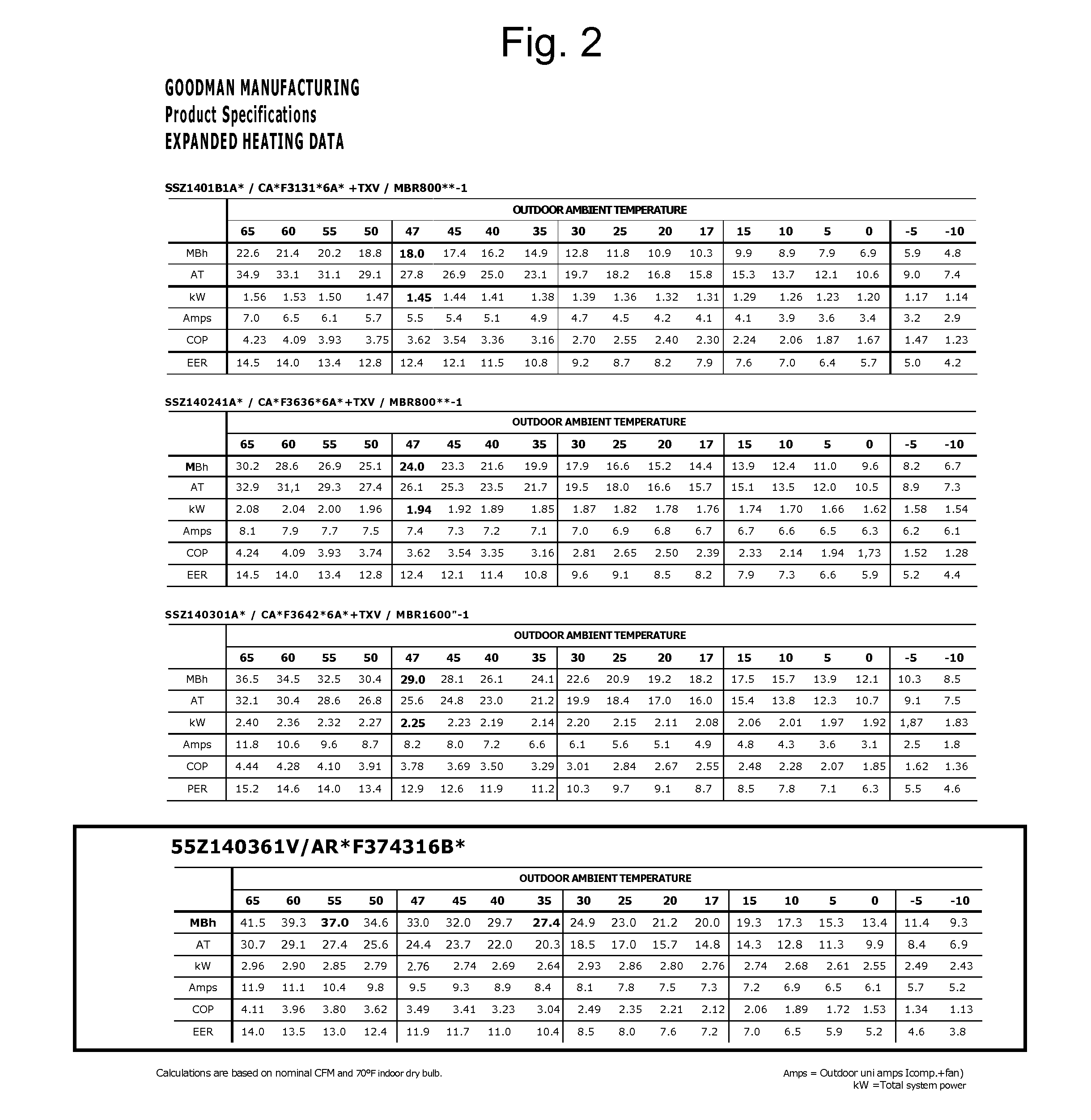
The fact that heating capacity of air-source heat pumps is marginal in climates much below 40 degrees Fahrenheit outdoor ambient temperature is well known in the HVAC industry; moreover, that heating capacity degrades precipitously with declining outdoor ambient temperature.
Thus, declining outside ambient temperature is one contributing cause of the fore mentioned shortfall.
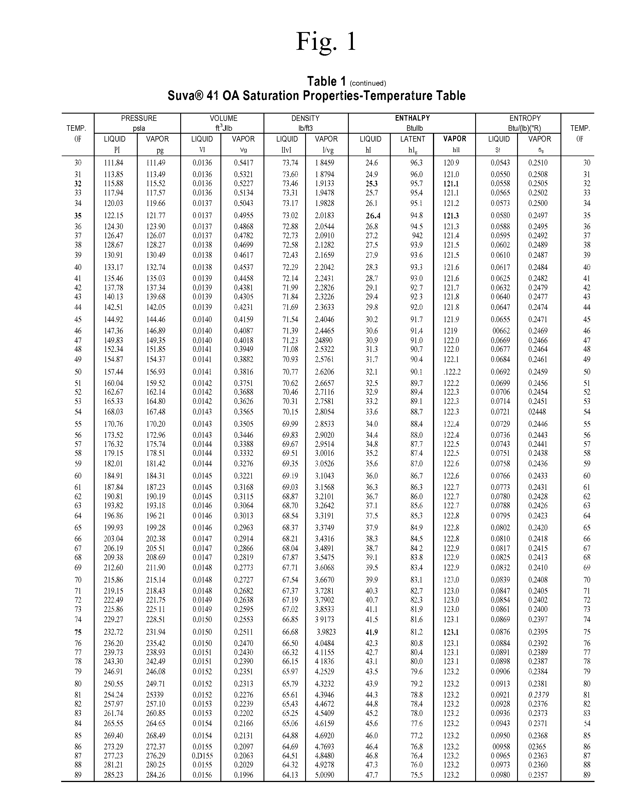
A second related cause of the shortfall is the generation of non-productive high specific volume vapor in the evaporator exacerbated by declining outdoor ambient temperature.
This residual heat energy causes a portion of the liquid to self-evaporate during the pressure reduction process, as it throttles from the expansion valve into the evaporator, creating a substantial volume of non-productive high specific volume vapor in the process.
However, the temperature of the liquid refrigerant entering the expansion valve is always at a substantially higher temperature than evaporating temperature and never less than conditioned air temperature, thus refrigeration effect is always less than the heat of vaporization and therefore always less than 100 percent efficient.
To make matters worse, the greater the differential between the temperature of the liquid condensate approaching the expansion valve and evaporating temperature the greater the quantity of liquid consumed during the pressure reduction process and thus the greater the volume of non-productive high specific volume vapor generated for the compressor to induct.
Obviously, that portion of the liquid already evaporated during the pressure reduction process is liquid that is no longer available to absorb heat energy from the outdoor ambient air.
Nevertheless, the resulting non-productive vapor must still pass through the system evaporator creating additional pressure drop and ultimately inducted and compressed to condensing level by the compressor.
Therefore, another factor contributing to the fore mentioned shortfall is generation of large quantities of non-productive high specific volume vapor in the evaporator that can easily reduce capacity 20 percent or more.
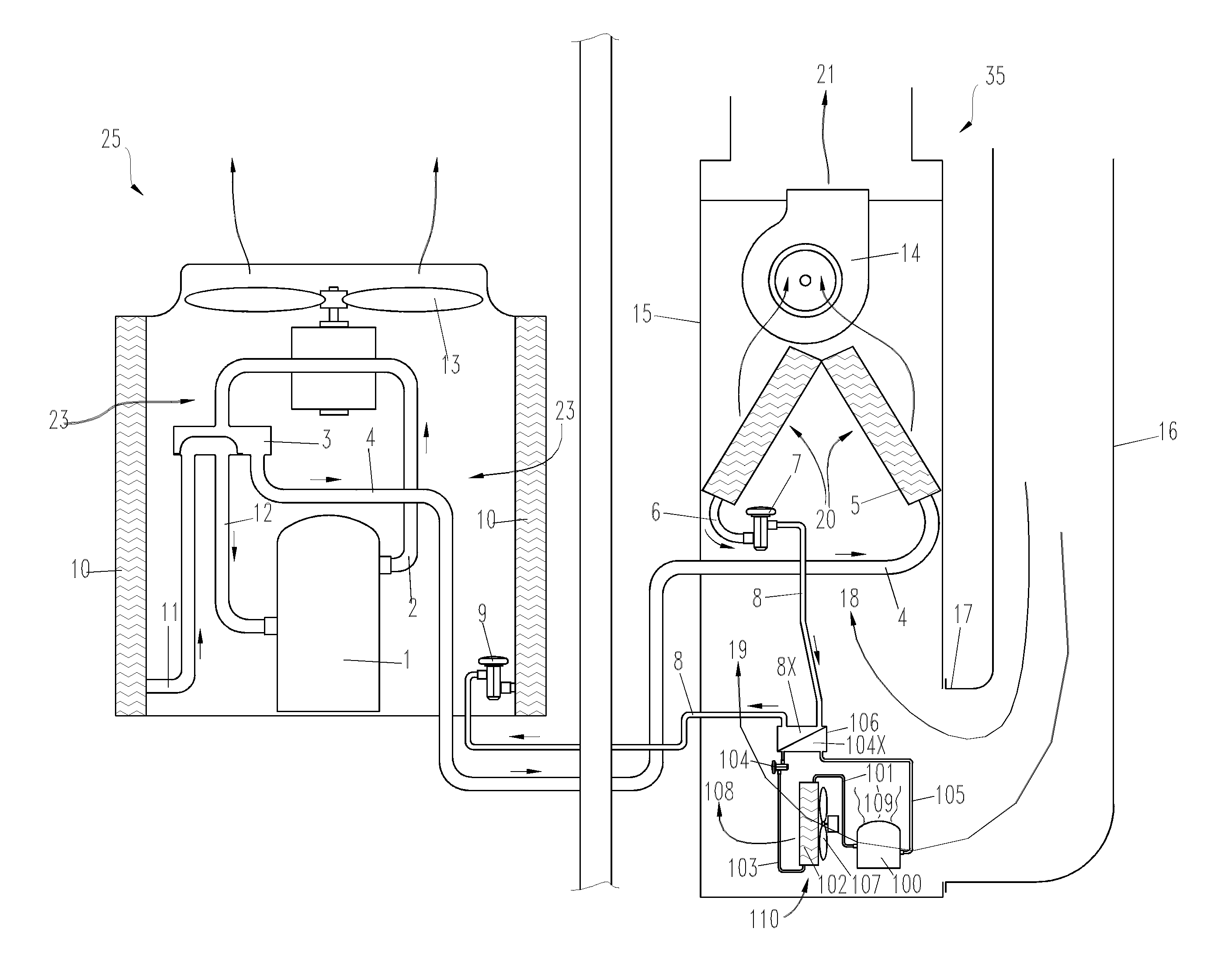
The only way to reduce or prevent formation of non-productive vapor in the evaporator is to minimize the temperature difference between the liquid entering the expansion valve and evaporating temperature, and this can only be accomplished by subcooling the liquid condensate before entering the expansion valve.
In other words, 12.7 percent of the vapor the compressor is required to pump is non-productive.
As previously stated, that portion of the liquid already evaporated during the pressure reduction process is liquid that is no longer available to absorb heat energy from the ambient air.
Nevertheless, the resulting non-productive high specific volume vapor must still pass through the system evaporator creating additional pressure drop and ultimately inducted and compressed to condensing level by the compressor.
However, the benefit of internal heat exchangers is limited and even questionable from an energetic point of view.
However, due to modest capacity gain and a relatively high performance penalty, powered subcooling has found little or no use in residential air conditioning and heat pump systems, and never in the heating cycle.
This is because subcooling is usually done within the context of refrigeration and air condition where saving excess heat is undesirable.
However, that's not all.

Method used


Image

  • Heat pump with independent subcooler circuit
  • Heat pump with independent subcooler circuit
  • Heat pump with independent subcooler circuit

Examples


Embodiment Construction

[0032]For the purpose of promoting an understanding of the principles of the invention, reference will now be made to the embodiments illustrated in the drawings and specific language will be used to describe the same. It will nevertheless be understood that no limitation of the scope of the invention is thereby intended. Any alterations and further modifications in the described embodiment, and any further applications of the principles of the invention as described herein are contemplated as would normally occur to one skilled in the art to which the invention relates. One embodiment of the invention is shown in great detail, although it will be apparent to those skilled in the relevant art that some features that are not relevant to the present invention may not be shown for the sake of clarity.

[0033]FIG. 4 illustrates one embodiment of an independent subcooler refrigeration circuit configured to work in conjunction with a primary refrigeration circuit operating in the heating mo...


PUM

PropertyMeasurementUnit
pressureaaaaaaaaaa
pressureaaaaaaaaaa
pressureaaaaaaaaaa

Abstract

An improved reversible cycle heat pump system incorporating powered subcooling to increase heating capacity by over 50 percent over conventional heat pump technology without imposing a performance penalty; wherein over 21 percent is attributable to evaporator capacity gained by subcooling, over 21 percent is attributable to recovery and utilization of sensible heat energy removed as a by-product of subcooling, and over 8 percent is attributable to recovery and utilization of sensible heat energy resulting from the conversion of electric energy to mechanical work, heat of compression, and mechanical heat of friction. The powered subcooling improvement is also easily installed as original equipment, or retrofitted to existing heat pump systems.

Description

BACKGROUND OF THE INVENTION[0001]Air-source heat pumps are the dominant heating source in the southern United States and in many places around the globe. They typically yield minimum vapor cycle efficiencies in excess of 200 percent and offer savings in operating expense over fossil fuel and direct electric heating systems. However, generally speaking heat pumps have been ignored in cold climates because their performance envelopes are limited to an ideal range, and falling outside that range on the heating side leads to high operating costs and discomfort in the conditioned space, i.e. home.[0002]In the southern parts of the United States, air-source heat pumps are known for their low operating costs. However, moving northward their advantage abates, and fossil fuel becomes more prevalent as a heating source. This is unfortunate for consumers. According to the U.S. Department of Energy's Energy Information Administration (EIA), over the past decade fossil fuel prices have increased...

Claims


Application Information

Patent Timeline
Patent Type & Authority Applications(United States)
IPC IPC(8): F25B29/00B23P15/26
CPCB23P15/26F25B7/00Y10T29/49359F25B40/02F25B30/02
Inventor ALBERTSON, LUTHER D.
Owner REDI CONTROLS
Why Eureka
Try Eureka