
Low inductance electrical transmission cable

a low-inductance, electrical transmission technology, applied in the direction of power cables, insulation conductors/cables, cables, etc., can solve the problems of inducing cancellation of inductive effects, and achieve the effects of low inductance properties, high current loads, and more uniform heating or loss profiles

Active Publication Date: 2014-03-13
FLEX CABLE
View PDF4 Cites 2 Cited by
  • Summary
  • Abstract
  • Description
  • Claims
  • Application Information

AI Technical Summary

Benefits of technology

The invention is an electrical transmission cable that has low inductance properties, which allows it to carry high current loads with more uniform heating or loss profiles. This results in a cooler and more efficient operation of the cable even at higher AC frequencies. The cable has a plurality of conductor bundles configured as braided wire strands that are separated and joined into like conductors prior to termination. The equal lengths of insulated wire strands within the conductor bundles contribute to uniform heating along the length of the cable. The cable also has a more equal weave position for all the wire strands, which tends to induce cancellation of inductive effects. It has been observed that external electromagnetic field (EMF) perturbations are at least partly occluded to the cable, reducing or eliminating the need for magnetic shielding of transmission cables. The cable can be used for various applications such as high frequency transformers for welders, inductive heaters, servo-motor power supply, magnetic resonance instrument power supply, and avionics.

Problems solved by technology

In addition, the more equal weave position for all the wire strands making up each braided wire bundle tends to induce cancellation of inductive effects.

Method used


Image

  • Low inductance electrical transmission cable
  • Low inductance electrical transmission cable
  • Low inductance electrical transmission cable

Examples


Embodiment Construction

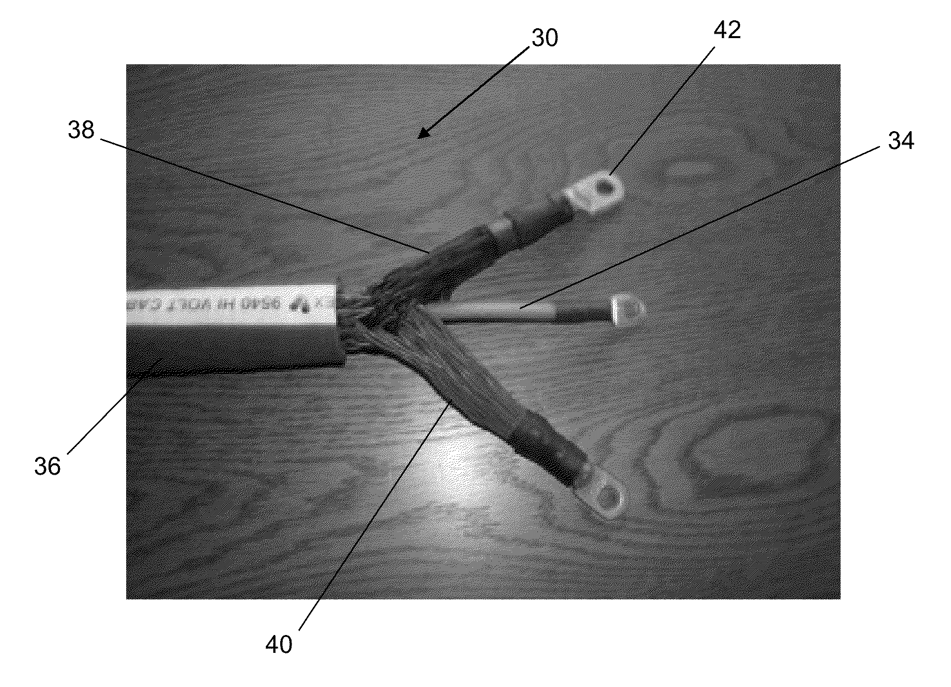
[0019]The present invention has utility as a low inductance electrical transmission cable. The low inductance properties of embodiments of the inventive cable lead to lower current losses resulting in a cooler and more efficient operation of the inventive cable even at higher alternating current (AC) frequencies. Higher current loads are accommodated by a plurality of conductor bundles configured as braided wire strands that are separated and joined into like conductors prior to termination. Equal lengths of the insulated wire strands within the conductor bundles contribute to uniform heating along the length of the inventive cable embodiments. Uniform operating temperature is manifest as more uniform current transmission across the various strands of an inventive cable. In addition, the more equal weave position for all the wire strands making up each braided wire bundle tends to induce cancellation of inductive effects. It has also been surprisingly observed that external electrom...


PUM

PropertyMeasurementUnit
skin depthaaaaaaaaaa
lengthsaaaaaaaaaa
conductiveaaaaaaaaaa

Abstract

An electrical transmission cable is provided with low inductance properties capable of carrying high current loads with a more uniform heating or loss profile. The low inductance properties of the cable lead to lower current losses resulting in a cooler and more efficient operation of the cable even at higher alternating current (AC) frequencies. Higher current loads are accommodated by a plurality of conductor bundles configured as braided wire strands that are separated and joined into like conductors prior to termination. Equal lengths of the insulated wire strands within the conductor bundles contribute to uniform heating along the length of the inventive cable embodiments. Uniform operating temperature is manifest as more uniform current transmission across the various strands of an inventive cable. In addition, the more equal weave position for all the wire strands making up each braided wire bundle tends to induce cancellation of inductive effects.

Description

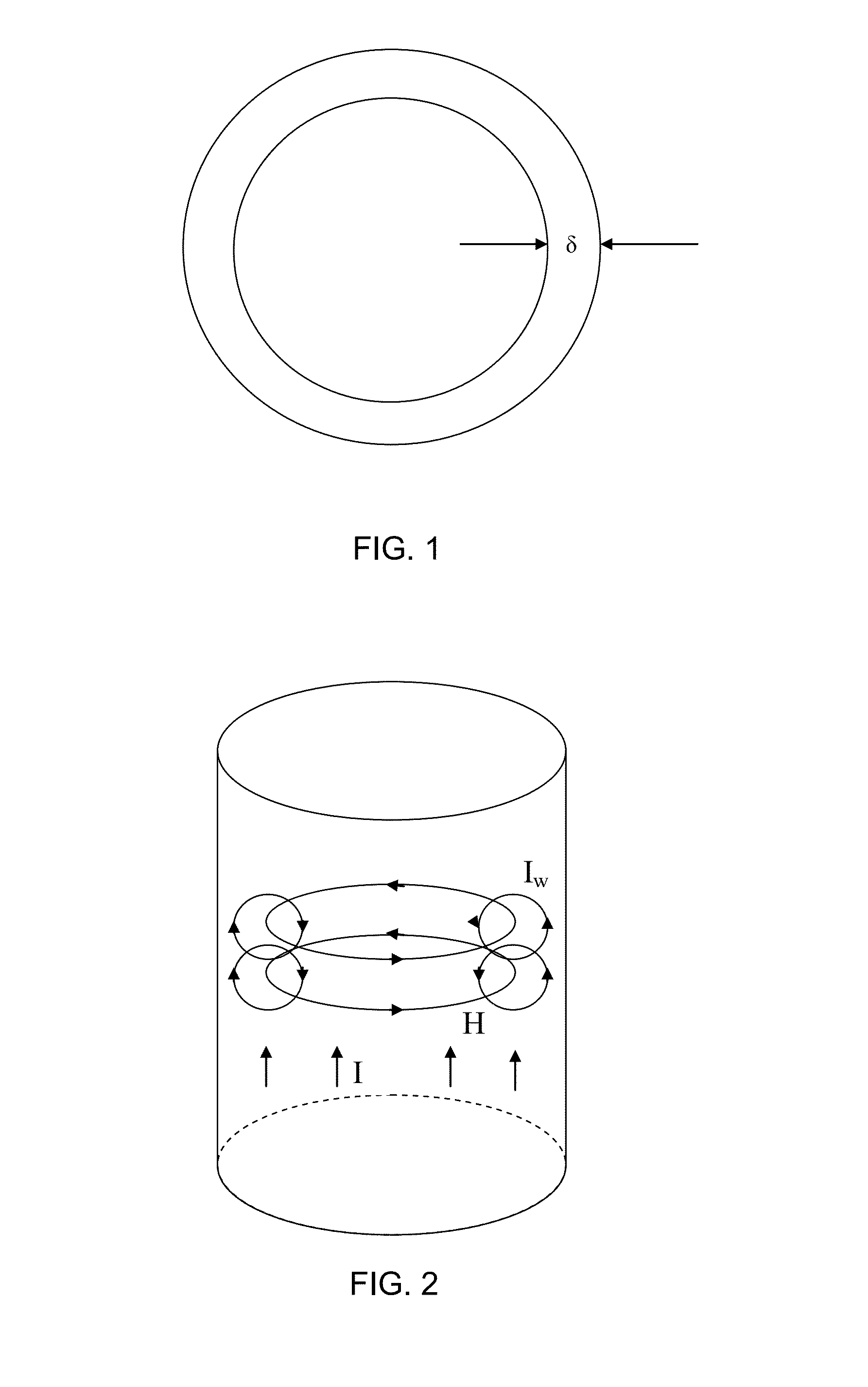
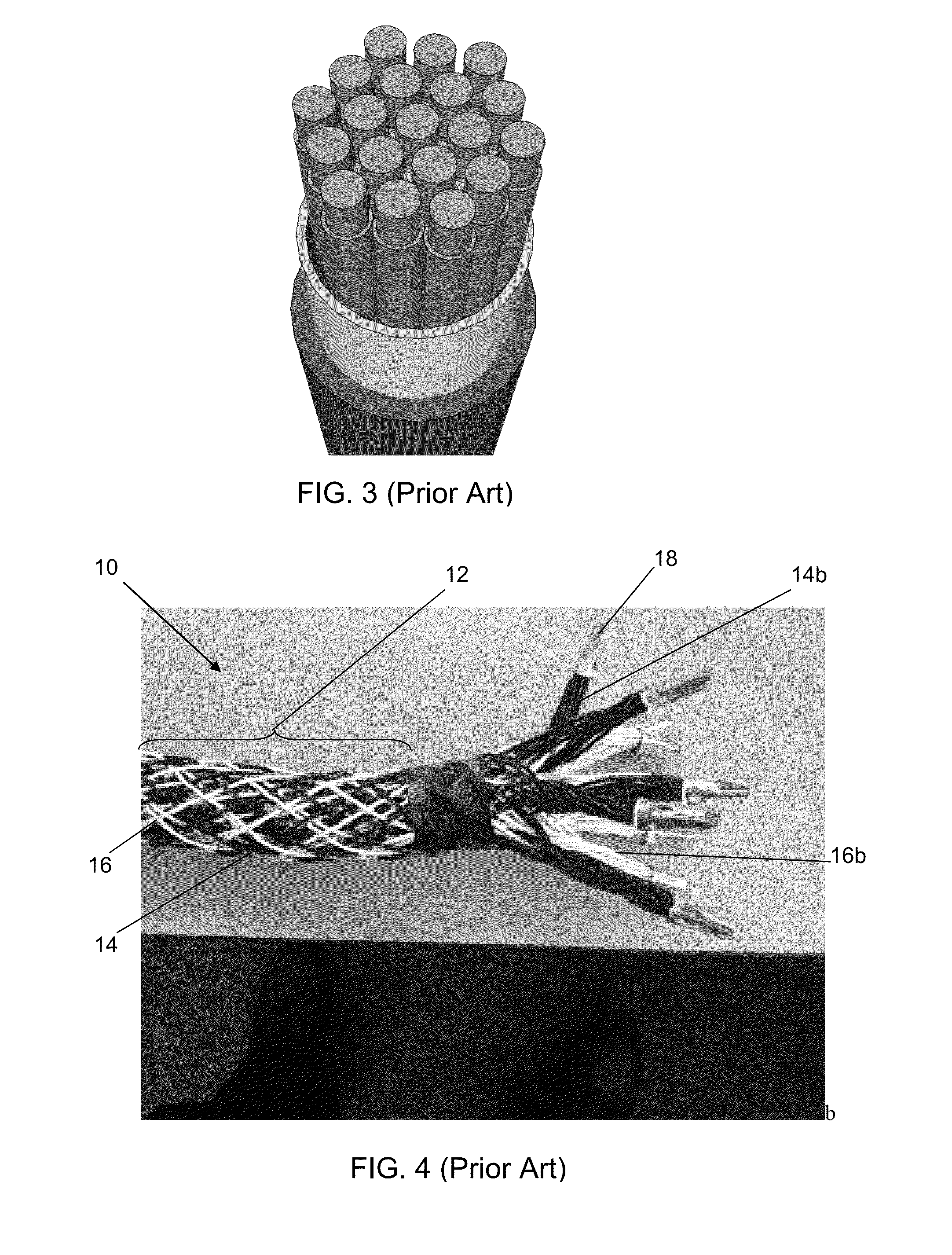
CROSS-REFERENCE TO RELATED APPLICATION[0001]This application claims priority of U.S. Provisional Patent Application Ser. No. 61 / 700,872 filed Sep. 13, 2012, which is incorporated herein by reference.FIELD OF THE INVENTION[0002]The present invention in general relates to electrical cables and in particular to electrical transmission with low inductance properties.BACKGROUND OF THE INVENTION[0003]Skin effect is the tendency of an alternating electric current (AC) to become distributed within a conductor such that the current density is largest near the surface of the conductor, and decreases with greater depths in the conductor. The electric current flows mainly at the “skin” of the conductor, between the outer surface and a level called the skin depth (δ) as shown in prior art FIG. 1. The skin effect causes the effective resistance of the conductor to increase at higher frequencies where the skin depth is smaller, thus reducing the effective cross-section of the conductor. For altern...

Claims


Application Information

Patent Timeline
Patent Type & Authority Applications(United States)
IPC IPC(8): H01B7/30H01B13/06
CPCH01B13/06H01B7/306H01B9/006H01R9/11Y10T29/49174
Inventor KROULIK, ERWIN
Owner FLEX CABLE
Learn More