Permanently excited synchronous machine with ferrite magnets

a synchronous machine and magnet technology, applied in the direction of dynamo-electric machines, magnetic circuit rotating parts, magnetic circuit shapes/forms/construction, etc., can solve the problem of high price of rare earth magnets, reduce torque ripple, and reduce the amplitude of magnetic field waves in the iron of the stator.

Active Publication Date: 2014-03-13
SIEMENS AG
View PDF2 Cites 8 Cited by
  • Summary
  • Abstract
  • Description
  • Claims
  • Application Information

AI Technical Summary

Benefits of technology

[0018]The design of the outer contour of the flux concentration elements also reduces the torque ripple and the amplitudes of the magnetic field waves in the iron of the stator are reduced, and this leads to comparatively low heating of the stator reduced by hysteresis and eddy current losses.

Problems solved by technology

However, rare earth magnets are very expensive, so attempts are made to switch to more inexpensive ferrite magnets.
This has proven difficult and required a rotor with a comparatively high number of poles to obtain a high air gap induction.

Method used


Image

  • Permanently excited synchronous machine with ferrite magnets
  • Permanently excited synchronous machine with ferrite magnets
  • Permanently excited synchronous machine with ferrite magnets

Examples


Embodiment Construction

[0024]Throughout all the figures, same or corresponding elements may generally be indicated by same reference numerals. These depicted embodiments are to be understood as illustrative of the invention and not as limiting in any way. It should also be understood that the figures are not necessarily to scale and that the embodiments are sometimes illustrated by graphic symbols, phantom lines, diagrammatic representations and fragmentary views. In certain instances, details which are not necessary for an understanding of the present invention or which render other details difficult to perceive may have been omitted.

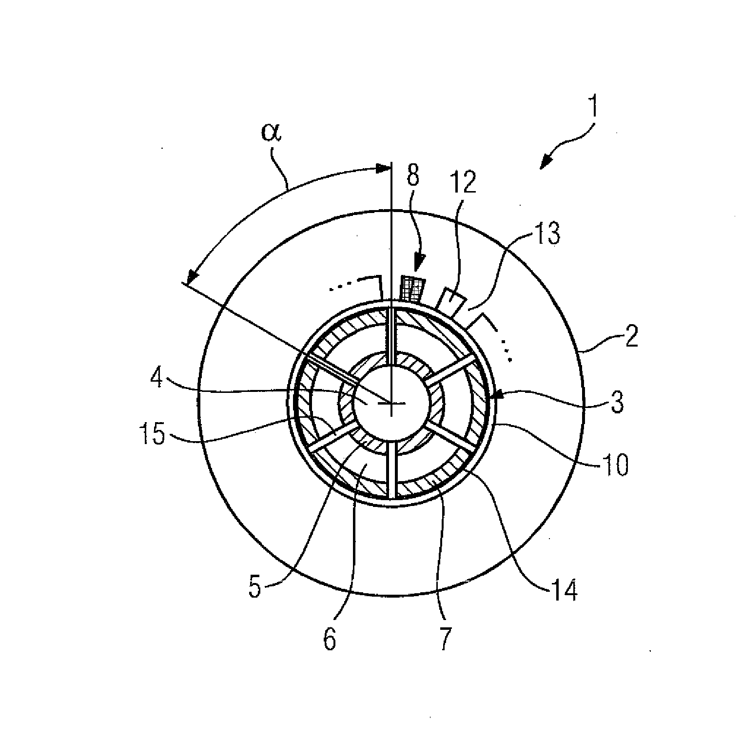
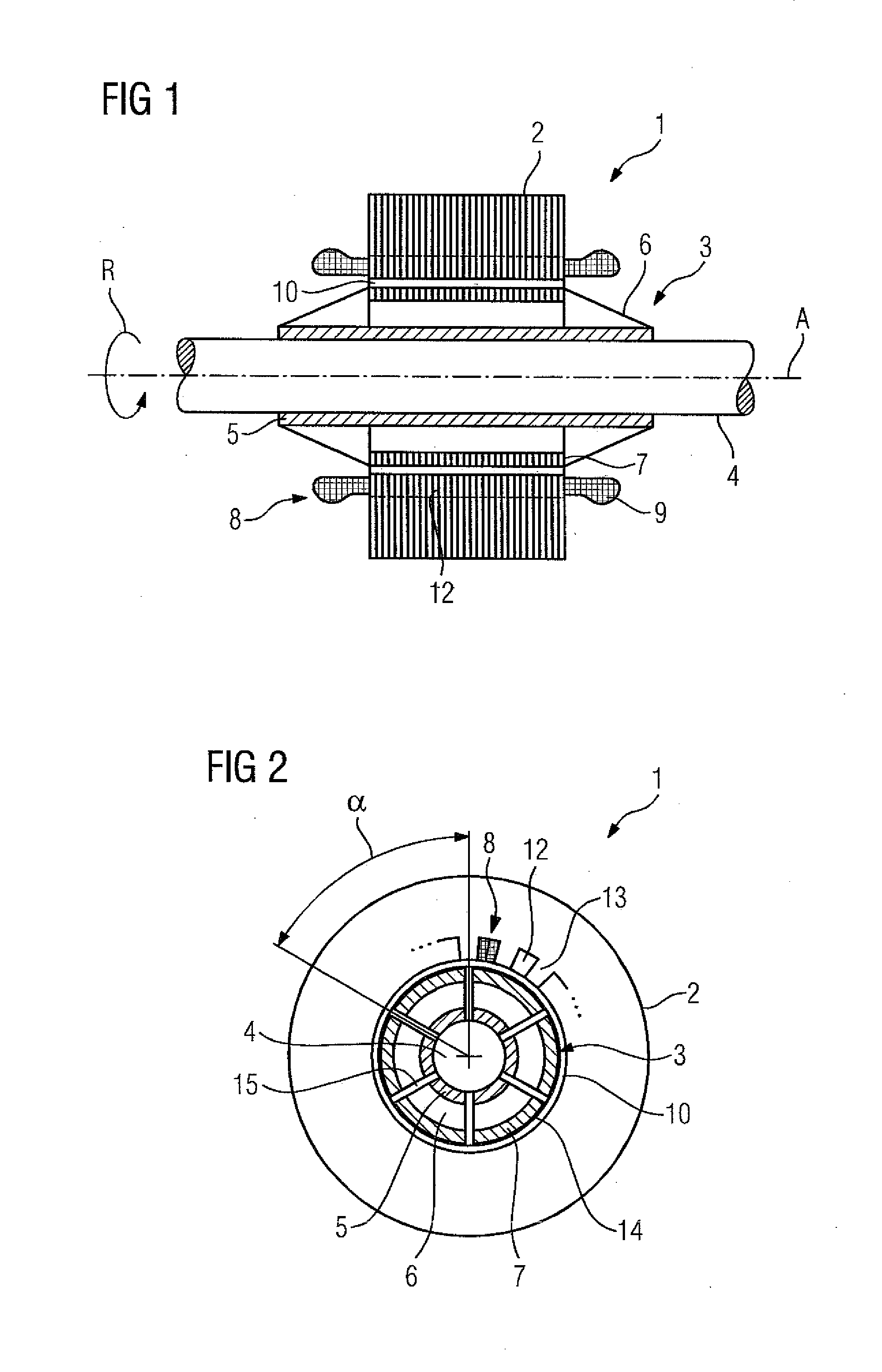
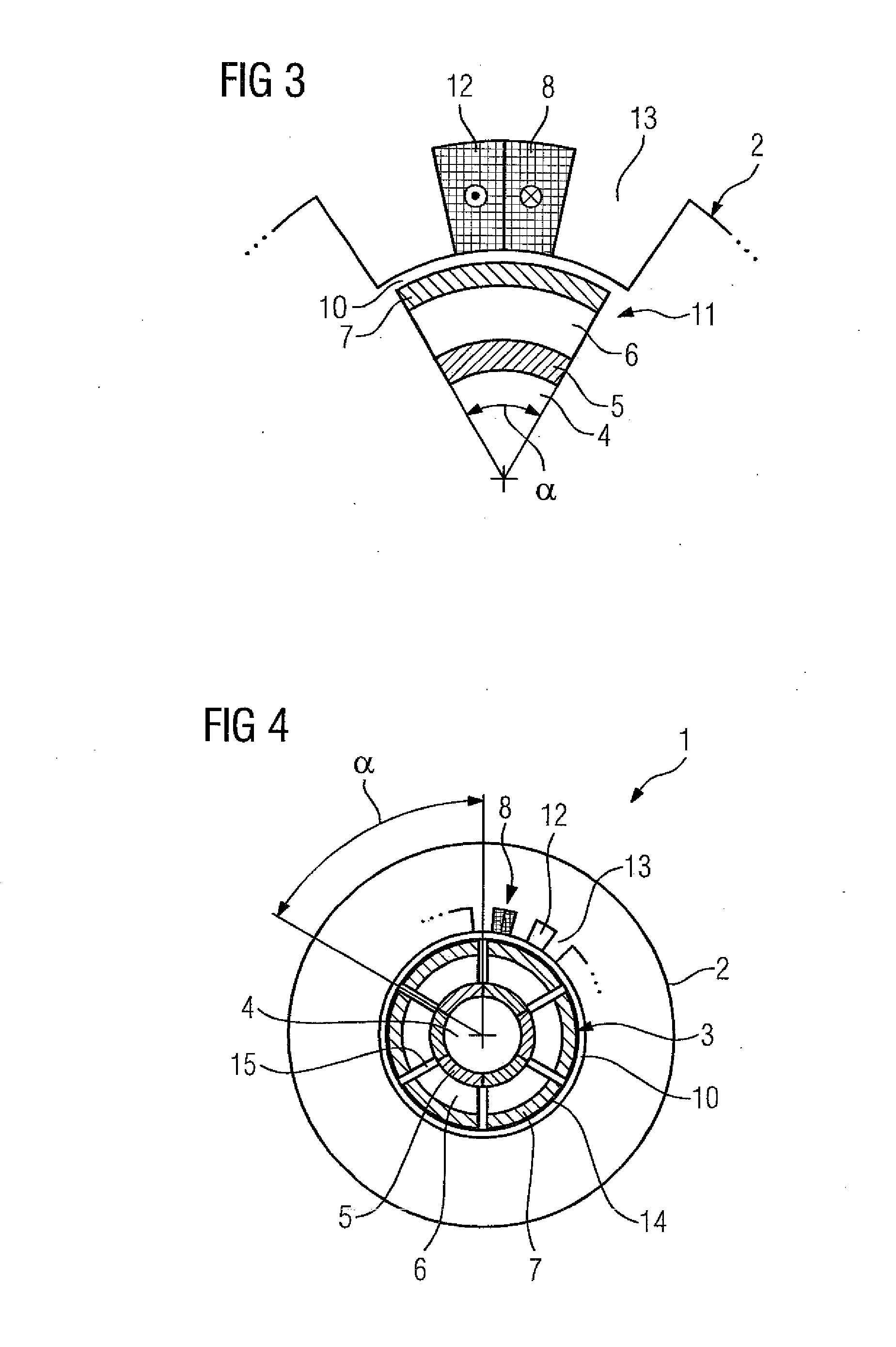
[0025]Turning now to the drawing, and in particular to FIG. 1, there is shown a longitudinal section of a basic configuration of permanently excited synchronous machine according to the present invention, generally designated by reference numeral 1. The permanently excited synchronous machine 1 includes a stator 2 and a winding system 8 which is embedded in grooves 12 of a l...


PUM


Abstract

A permanently excited synchronous machine includes a stator; a winding system arranged in grooves of a laminated core of the stator and forming winding overhangs on end faces of the laminated core, and a rotor connected in fixed rotative engagement to the shaft and having ferrite magnets which extend axially beyond the end faces of the laminated core. The rotor electromagnetically interacts with the stator across an air gap there between during operation of the permanently excited synchronous machine to cause a rotation about an axis of rotation. A flux concentration element is provided radially across each of the ferrite magnets of a magnetic pole and bundles magnetic field lines of the ferrite magnet onto an axial length of the laminated core of the stator. The flux concentration elements and held by a fixing element on the ferrite magnets of a magnetic pole.

Description

CROSS-REFERENCES TO RELATED APPLICATIONS[0001]This application claims the priority of European Patent Application, Serial No. EP 12184270.2, filed Sep. 13, 2013, pursuant to 35 U.S.C. 119(a)-(d), the disclosure of which is incorporated herein by reference in its entirety as if fully set forth herein.BACKGROUND OF THE INVENTION[0002]The present invention relates to a permanently excited synchronous machine.[0003]The following discussion of related art is provided to assist the reader in understanding the advantages of the invention, and is not to be construed as an admission that this related art is prior art to this invention.[0004]Rare earth magnets can be used to obtain a high air gap induction with permanently excited synchronous machines. However, rare earth magnets are very expensive, so attempts are made to switch to more inexpensive ferrite magnets. This has proven difficult and required a rotor with a comparatively high number of poles to obtain a high air gap induction.[000...

Claims


Application Information

Patent Timeline
Patent Type & Authority Applications(United States)
IPC IPC(8): H02K1/27
CPCH02K1/272H02K21/14H02K1/2766H02K2201/03
Inventor SCHNEIDER, WOLFGANGVOLLMER, ROLF
Owner SIEMENS AG
Why Eureka
Try Eureka