Axial split-phase bearingless flywheel motor of three phases and four degrees of freedom

a flywheel motor and split-phase technology, applied in the direction of windings, magnetic circuit rotating parts, magnetic circuit shapes/forms/construction, etc., can solve the problems of reduced critical speed of rotation, complex structure of flywheel batteries, and many technical problems of fes technology, so as to reduce torque ripple and enhance torque output

Active Publication Date: 2020-04-16
NANJING INST OF TECH
View PDF0 Cites 1 Cited by
  • Summary
  • Abstract
  • Description
  • Claims
  • Application Information

AI Technical Summary

Benefits of technology

[0012]In the present invention, the stator and the rotor are axially divided into three sections: a phase A, a phase B and a phase C. The phase A and the phase C are both provided with suspension poles and torque poles, and the stator core in the phase B is provided with twelve torque poles of a uniform width at equal intervals. In this way, the present invention realizes self-starting and suspension at four degrees of freedom, reduces the torque ripple, and enhances the torque output.

Problems solved by technology

However, the FES technology still has many technical problems, including implementation of a suspension support system.
As a result, the critical speed of rotation is reduced, and the structure of a flywheel battery is complicated.
However, at present, the BSRMs are not widely popularized in FES-related practical engineering applications both at home and abroad.
The main reason is that strong and complicated electromagnetic coupling exists between windings, magnetic circuits, and the electromagnetic force inside the motor, increasing the difficulty in analysis and high-speed control for the motor, which immensely restricts the entry of the BSRMs into engineering applications.
For example, the dual-stator structure increases the difficulty in integration of the motor and the flywheel; the hybrid-rotor structure still has a long axial length, limiting the critical speed of rotation of the flywheel; and in the hybrid-stator structure and the permanent magnet biased structure, the suspension poles occupy much space, and the motor outputs limited torque and power, adversely affecting flywheel operation under conditions of fast charging and discharging.
However, the improved structure proposed by this invention is a two-phase structure, which does not have a self-starting property and outputs low-density and high-ripple torque, thus affecting the operation of the flywheel during charging and discharging.

Method used


Image

  • Axial split-phase bearingless flywheel motor of three phases and four degrees of freedom
  • Axial split-phase bearingless flywheel motor of three phases and four degrees of freedom
  • Axial split-phase bearingless flywheel motor of three phases and four degrees of freedom

Examples


Embodiment Construction

[0021]To further understand the present invention, the present invention will be further described in detail below with reference to the accompanying drawings and specific embodiments. The embodiments are merely used for explaining the present invention, and do not constitute improper limitations to the scope of protection of the present invention.

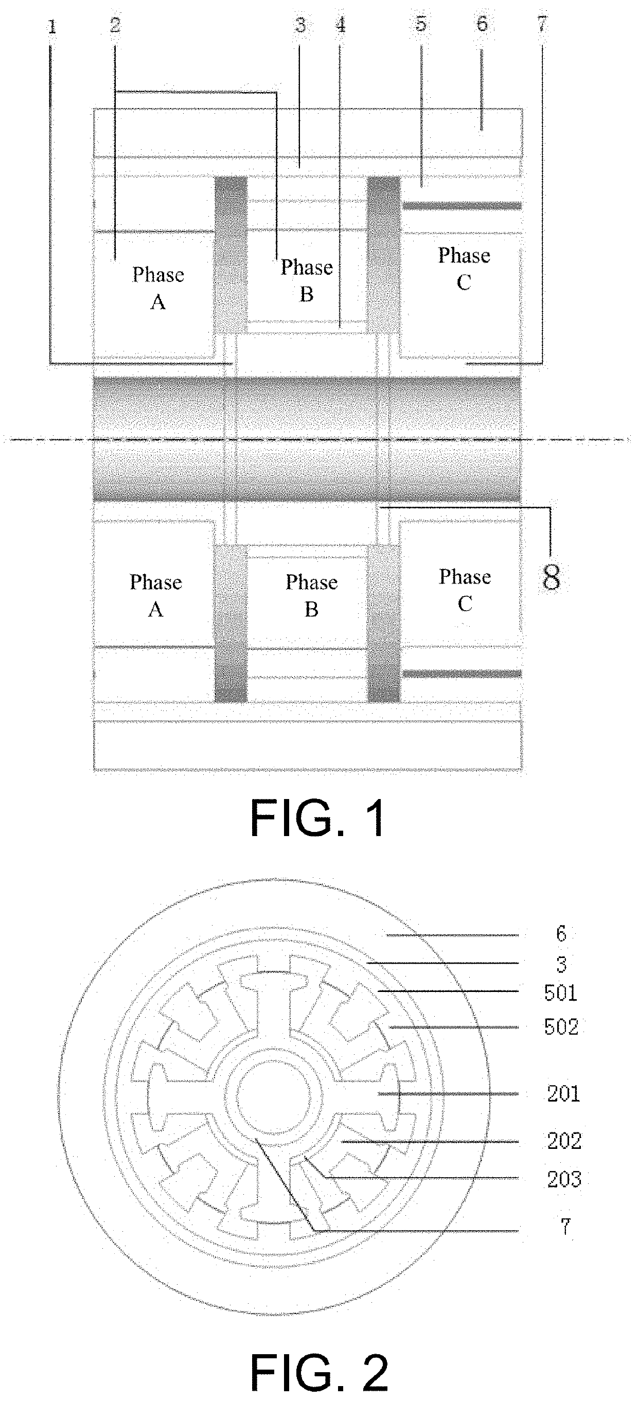
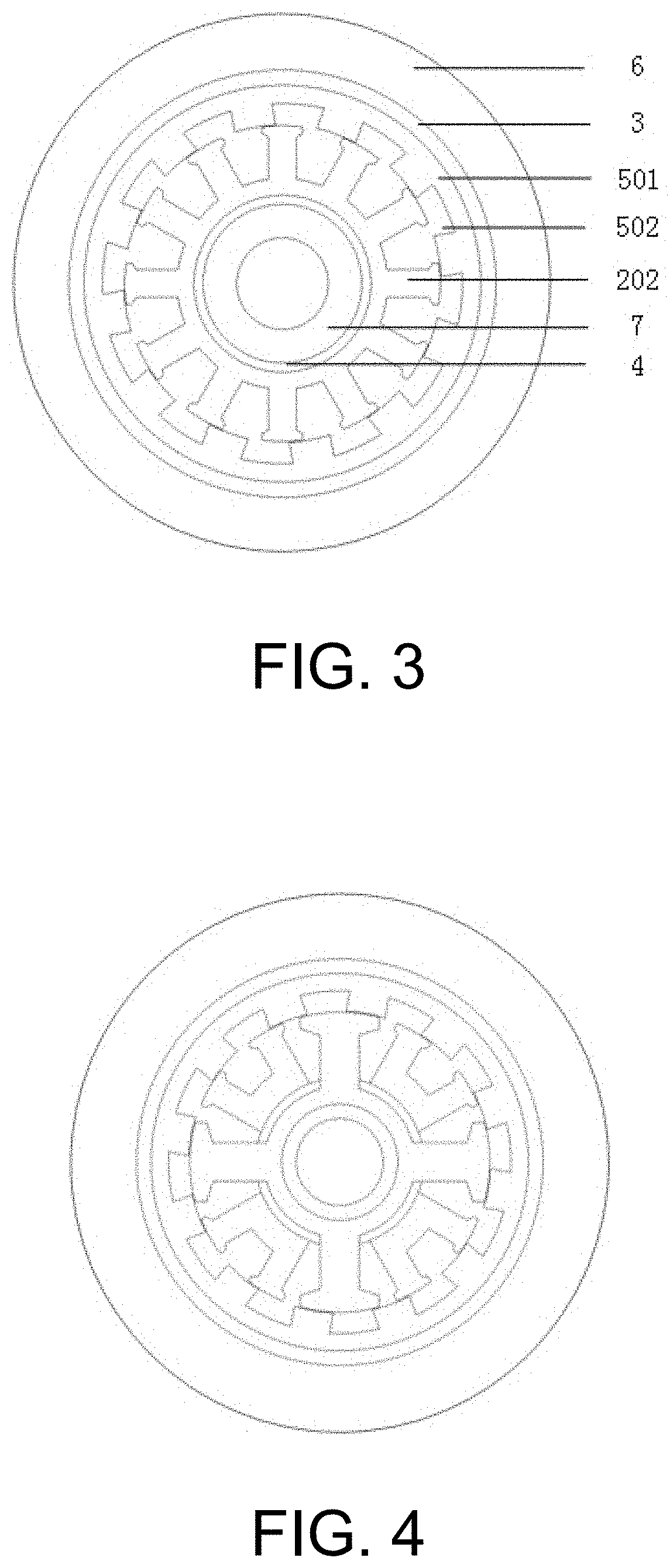
[0022]As shown in FIG. 1 to FIG. 7, the present invention provides an axial split-phase bearingless flywheel motor of three phases and four degrees of freedom, which includes a stator 2, a stator sleeve 7, a rotor 5, a rotor sleeve 3, and a flywheel 6. The rotor core, the rotor sleeve 3, and the flywheel 6 are concentrically nested as a whole from inside to outside, and a stator core and the stator sleeve 7 are concentrically nested on a stationary shaft. The stator 2 and the rotor 5 are axially divided into three sections: a phase A, a phase B, and a phase C. An axially magnetized permanent magnet is provided between every adjacent phases...


PUM


Abstract

An axial split-phase bearingless flywheel motor includes a stator, a stator sleeve, a rotor, a rotor sleeve, and a flywheel. The stator and the rotor are axially divided into phases A, B and C. An axially magnetized permanent magnet is provided between every adjacent phases. Twelve rotor poles are provided at equal intervals on an inner side of the rotor core in each of the phases A, B, and C. The rotor poles in the phases A, B and C are staggered in sequence along a circumference by ⅓ of a rotor pole pitch. Eight torque poles in a shape of narrow teeth and four suspension poles in a shape of wide teeth are provided on the stator core in both the phases A and C, and twelve torque poles of a uniform width are provided on the stator core in the phase B.

Description

BACKGROUNDTechnical Field[0001]The present invention relates to the field of bearingless motors, and in particular, to an axial split-phase bearingless flywheel motor of three phases and four degrees of freedom.Description of Related Art[0002]With the development of fields such as new energy generation, distributed power systems, hybrid vehicles, and aerospace, energy storage technologies have become a global hot research topic. Among various energy storage technologies, flywheel energy storage (FES) is highly valued both at home and abroad due to such advantages as high efficiency, great power, long service life, high energy storage density, and no pollution. However, the FES technology still has many technical problems, including implementation of a suspension support system. In order to reduce the loss in suspension support, an FES system generally uses a plurality of magnetic bearings, which inevitably prolongs a flywheel rotor in an axial direction. As a result, the critical sp...

Claims


Application Information

Patent Timeline
Patent Type & Authority Applications(United States)
IPC IPC(8): H02K7/02H02K3/28H02K1/27H02K1/30H02K1/22H02K1/18H02K3/47
CPCH02K3/47H02K1/30H02K7/025H02K1/2726H02K1/18H02K3/28H02K1/223H02K3/04H02K7/09H02K21/44
Inventor ZHU, ZHIYINGSUN, YUKUNHAO, SIPENGCHEN, MINGZHU, JINZHU, HAILANG
Owner NANJING INST OF TECH
Why Eureka
Try Eureka