Controller for motor
a technology for controlling devices and motors, applied in the direction of motor/generator/converter stoppers, dynamo-electric gear control, motor/generator/converter stoppers, etc., can solve the problems of increasing torque ripple, vibration noise, and magnetic imbalance of the rotor, and achieve the effect of reducing torque rippl
- Summary
- Abstract
- Description
- Claims
- Application Information
AI Technical Summary
Benefits of technology
Problems solved by technology
Method used
Image
Examples
first embodiment
[0019]A first embodiment according to the present invention will now be discussed with reference to the drawings.
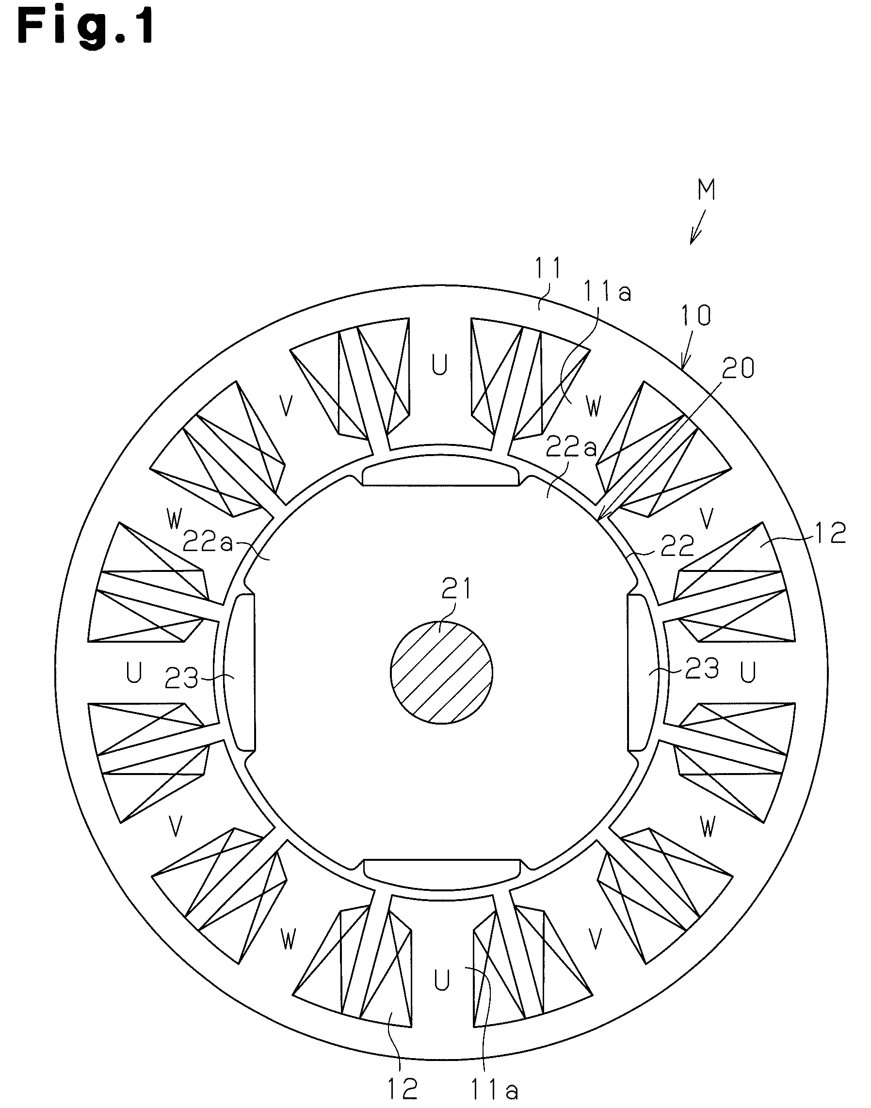
[0020]As shown in FIG. 1, a motor M of the present embodiment is of an inner rotor type and includes a stator 10 and a rotor 20, which is rotatably accommodated inside the stator 10. The stator 10 includes an annular stator core 11, which is formed from a magnetic metal, and twelve coils 12, which are wound as a concentrated winding around twelve teeth lla arranged at equal angular intervals on the stator core 11. The twelve coils 12 are arranged in order as a U-phase coil, a W-phase coil, and a V-phase coil in the clockwise direction in FIG. 1. The coils 12 are supplied with excitation currents Iu, Iw, Iv for a U-phase, W-phase, and V-phase, respectively. The U-phase, W-phase, and V-phase have phase differences of 120° from one another.
[0021]The rotor 20 includes a rotation shaft 21, a rotor core 22 formed from a magnetic metal and fixed to the rotation shaft 21, and fou...
second embodiment
[0036]A second embodiment of the present invention will now be discussed with reference to the drawings.
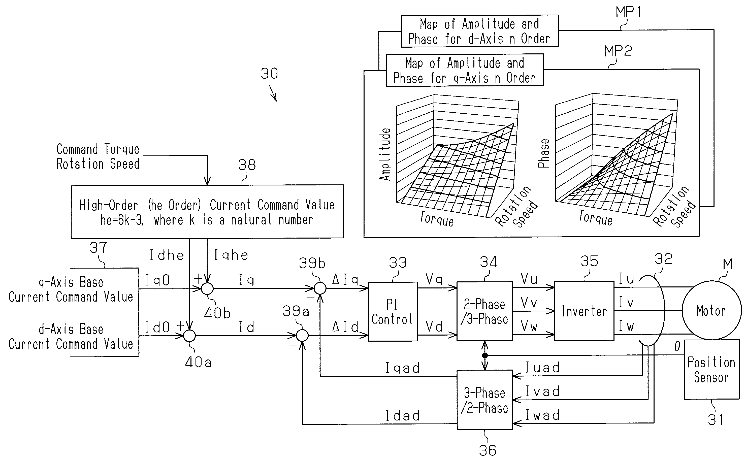
[0037]As shown in FIG. 4, in a controller 30a of the second embodiment, the high-order current calculation unit 38 calculates the high-order current command value Iqhe of the third order and the ninth order that cancels the third order and ninth order components of the torque ripple only for the q-axis. Further, the high-order current calculation unit 38 adds the high-order current command value Iqhe to the q-axis target current command value Iq. Accordingly, the controller 30a of the second embodiment has a simplified structure in which the map MP1 and the adder 40a for the d-axis side used in the first embodiment are eliminated. In the second embodiment, the high-order current calculation unit 38 and the adder 40b function as the current adjustment unit.
[0038]In FIG. 5A, a solid line indicates the change in current of the excitation currents Iu (Iv and Iw) when the present contr...
third embodiment
[0043]A third embodiment of the present invention will now be discussed with reference to the drawings.
[0044]As shown in FIG. 6, in a controller 30b of the third embodiment, a high-order (ho order) current calculation unit 41 is used in addition to the high-order (he order) current calculation unit 38. The order (ho) of high-order current command values Idho and Iqho calculated by the high-order (ho order) current calculation unit 41 is ho=6k (k is a natural number). In the third embodiment, the current command values of k=1, 2, that is, the sixth order and twelfth order are calculated.
[0045]More specifically, in the controller 30b of the third embodiment, the high-order (he order) current calculation unit 38 calculates the high-order current command values Idhe and Iqhe of the third order and the ninth order for d and q-axes that cancel the third order and ninth order components of the torque ripple. In addition, the high-order (ho order) current calculation unit 41 calculates the ...
PUM
 Abstract
Description
Claims
Application Information
 - R&D
- Intellectual Property
- Life Sciences
- Materials
- Tech Scout
- Unparalleled Data Quality
- Higher Quality Content
- 60% Fewer Hallucinations
Browse by: Latest US Patents, China's latest patents, Technical Efficacy Thesaurus, Application Domain, Technology Topic, Popular Technical Reports.
© 2025 PatSnap. All rights reserved.Legal|Privacy policy|Modern Slavery Act Transparency Statement|Sitemap|About US| Contact US: help@patsnap.com


