Electric motor

a technology of electric motors and coupling motors, applied in the direction of synchronous motors, magnetic circuit rotating parts, magnetic circuit shapes/forms/construction, etc., can solve the problems of significant acoustic noise, internal combustion engine vehicles will eventually have to be replaced by alternative fuel vehicles, and carbon dioxide emissions from electric vehicles are only 30% to 50% of internal combustion engine vehicles. , to achieve the effect of reducing torque ripple, reducing manufacturing costs, and lightening weigh

Inactive Publication Date: 2018-01-04
THE HONG KONG POLYTECHNIC UNIV
View PDF2 Cites 3 Cited by
  • Summary
  • Abstract
  • Description
  • Claims
  • Application Information

AI Technical Summary

Benefits of technology

[0009]Advantageously, an electric motor according to the present invention can create both attractive and repulsive forces between a stator resonant circuit and a rotor resonant circuit in the motor operation which significantly reduces torque ripple. Furthermore, an electric motor according to the present invention does not require ferromagnetic material to operate and will does not therefore suffer from flux saturation problems. Additionally, since no ferromagnetic material or expensive permanent magnets are required, an electric motor according to the present invention lighter in weight and lower in manufacture cost than existing electric motor designs. Further still, the power level of an electric motor according to the present invention is theoretically unlimited.

Problems solved by technology

In addition, carbon dioxide emissions from electric vehicles are only 30% to 50% of internal combustion engine vehicles.
Besides that, as fossil fuels are a finite resource and will inevitably run out, internal combustion engine vehicles will ultimately have to be replaced by alternative fuel vehicles.
A problem with SRMs is that they are based on a double salient structure which causes significant acoustic noise compared with other machines.
Furthermore, because an SRM uses attractive forces only to drive the rotor to rotate, it suffers from torque ripple and low power density.
However, increasing the shaft speed and, hence, rotational speed can give rise to large centrifugal forces on the rotor and its various elements that can cause the motor to crash.
A further disadvantage of a PMSM is that it requires relatively expensive permanent magnets which limit the power level (typically tens of kilowatts) and which also suffer from demagnetisation when subjected to high temperatures.

Method used


Image

  • Electric motor
  • Electric motor
  • Electric motor

Examples


Embodiment Construction

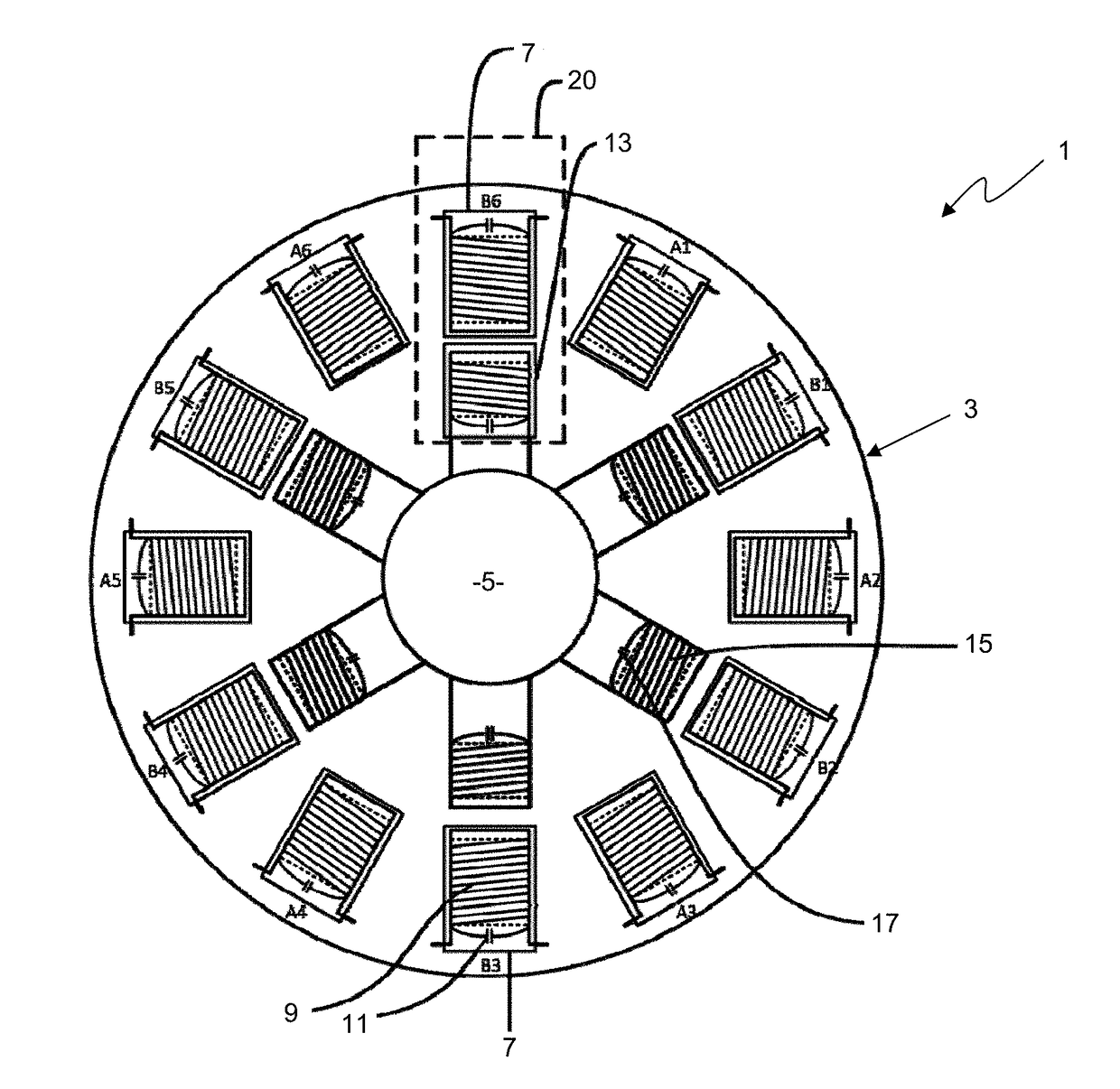
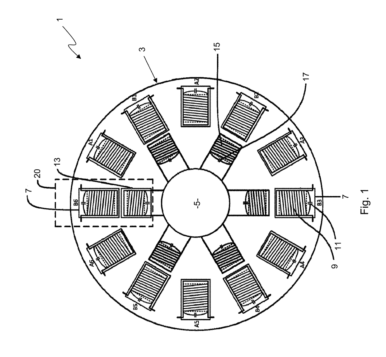
[0053]Referring to the drawings, FIG. 1 shows a magnetic resonant coupling motor or electric motor 1 comprising a stator 3 and a rotor 5. The stator 3 comprises twelve substantially cylindrical stator salient poles 7 having a radius of approximately 0.03 m and a length of approximately 0.05 m. The stator salient poles 7 are arranged in a ring such that the longitudinal axis of each stator salient pole 7 is directed toward the approximate centre of the stator 3. The stator salient poles 7 are equally spaced apart about the centre of the stator 3 such that the angle between the longitudinal axes of two adjacent stator poles is 30°. The stator 3 is chosen to have an inner diameter of approximately 0.245 m as measured from the inner extremity of one stator salient pole 7 to the inner extremity of another stator salient pole 7 on the opposite side respectively of the stator 3.

[0054]The stator salient poles 7 are made from a non-ferromagnetic material such as Bakelite® or reinforced, rigi...


PUM


Abstract

An electric motor comprising a stator and a rotor. The stator has at least one resonant circuit and the rotor has at least one resonant circuit rotatable with the rotor relative to at least one stator resonant circuit such that at least one rotor resonant circuit is angularly displaceable relative to at least one stator resonant circuit. At least one stator resonant circuit and at least one rotor resonant circuit are configured to have at least substantially the same self-resonant frequency. The electric motor uses magnetic resonant coupling between one or more stator resonant circuits and one or more rotor resonant circuits to produce usable torque.

Description

FIELD OF THE INVENTION[0001]The present invention relates to electric motors and, in particular, magnetic resonant coupling motors.BACKGROUND OF THE INVENTION[0002]Electric motors have a wide range of applications in a diverse range of industries including automotive, machine tools, fans, refrigerators, pumps, industrial equipment and even toys. In recent times, there has been a particular focus on electric motors in the automotive industry. One of the key reasons for this is the global push to reduce worldwide carbon emissions. Due to expected increases in global temperatures, which are believed to be directly related to carbon emissions, conventional internal combustion engines that derive their energy from fossil fuels are responsible for a large proportion of greenhouse gas emissions and are gradually being replaced by electric motors in electric vehicles.[0003]Electric vehicles have a number of advantages over conventional internal combustion engine vehicles. From an efficiency...

Claims


Application Information

Patent Timeline
Patent Type & Authority Applications(United States)
IPC IPC(8): H02K19/12H02K1/24H02K1/14
CPCH02K19/12H02K1/24H02K1/14
Inventor LIU, MINGCHAN, HON LUNGCHAN, KA WINGLIU, JUNWEIXU, WENZHENG
Owner THE HONG KONG POLYTECHNIC UNIV
Why Eureka
Try Eureka