Control apparatus for electric motor

a control apparatus and electric motor technology, applied in the direction of motor/generator/converter stopper, dynamo-electric gear control, dynamo-electric converter control, etc., can solve the problems of low switching frequency and small switching loss, so as to reduce the torque ripple reduce the loss caused by the response delay of the electric motor, and reduce the effect of loss

Active Publication Date: 2014-06-10
HONDA MOTOR CO LTD
View PDF19 Cites 2 Cited by
  • Summary
  • Abstract
  • Description
  • Claims
  • Application Information

AI Technical Summary

Benefits of technology

[0026]According to the control apparatus for the electric motor according to the invention described in claims 1 to 8, even when the rectangular wave inverter performs 1 PLS control, a loss caused by a response delay of the electric motor can be reduced. That is, the voltage converting section outputs an electrical-angle synchronized voltage whose amplitude ripples in synchronization with a change of the electrical angle of the rotator of the electric motor. This reduces the torque ripple of the electric motor caused by the change of the electrical angle, and hence reduces the loss caused by the slow response of the torque. Further, since the torque ripple is reduced, noise and vibration of the electric motor 10 are reduced.
[0027]According to the control apparatus for the electric motor according to the invention described in claims 4 to 7, an electrical angle acquiring section that acquires the electrical angle of the rotator of the electric motor is not provided. Thus, the output voltage command generating section can generate an electrical-angle synchronized voltage command not affected by an error in the electrical angle acquiring section.

Problems solved by technology

On the other hand, in the 1 PLS control, the switching frequency is low and hence a switching loss is small.

Method used


Image

  • Control apparatus for electric motor
  • Control apparatus for electric motor
  • Control apparatus for electric motor

Examples


first embodiment

[0048](First Embodiment)

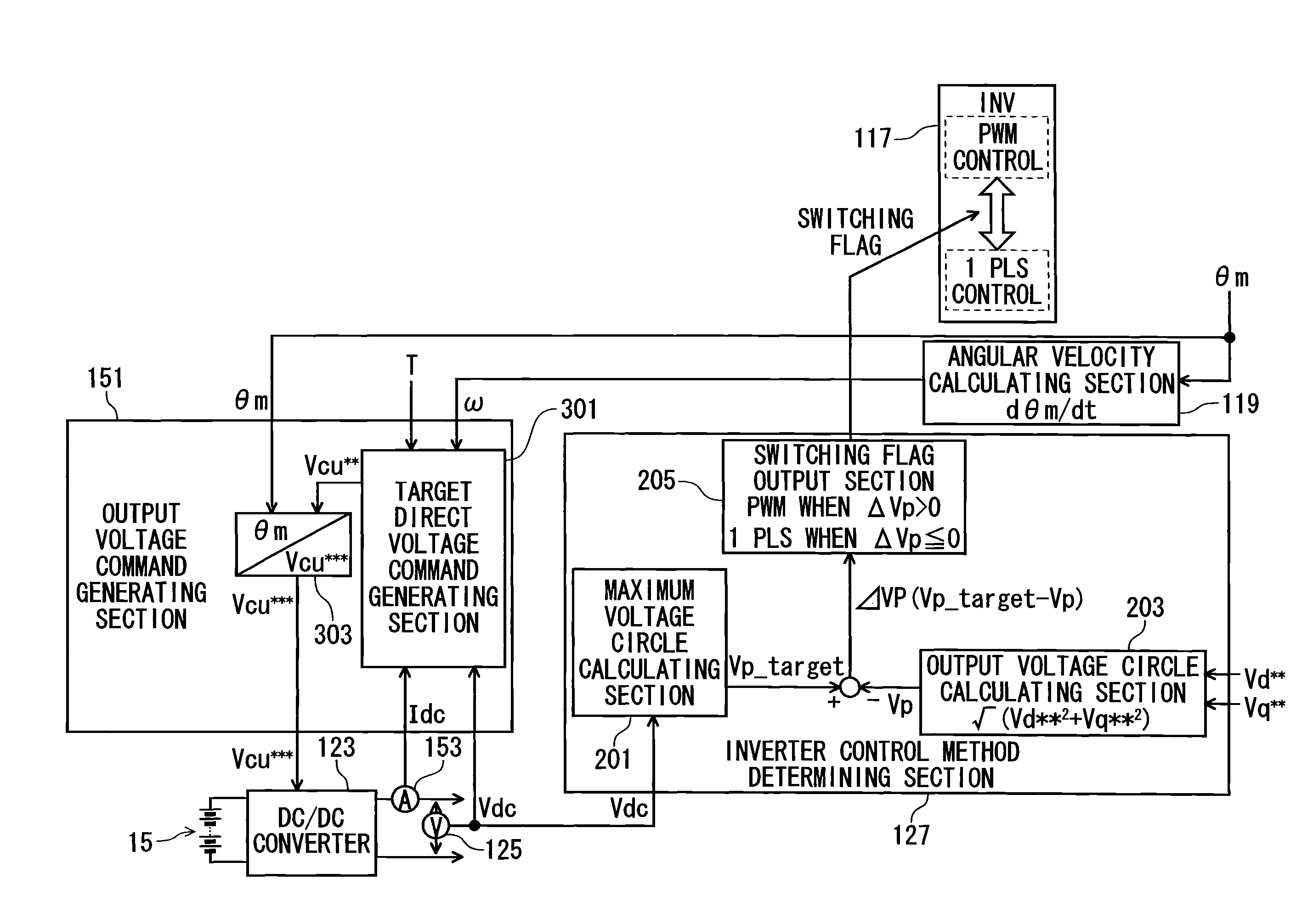
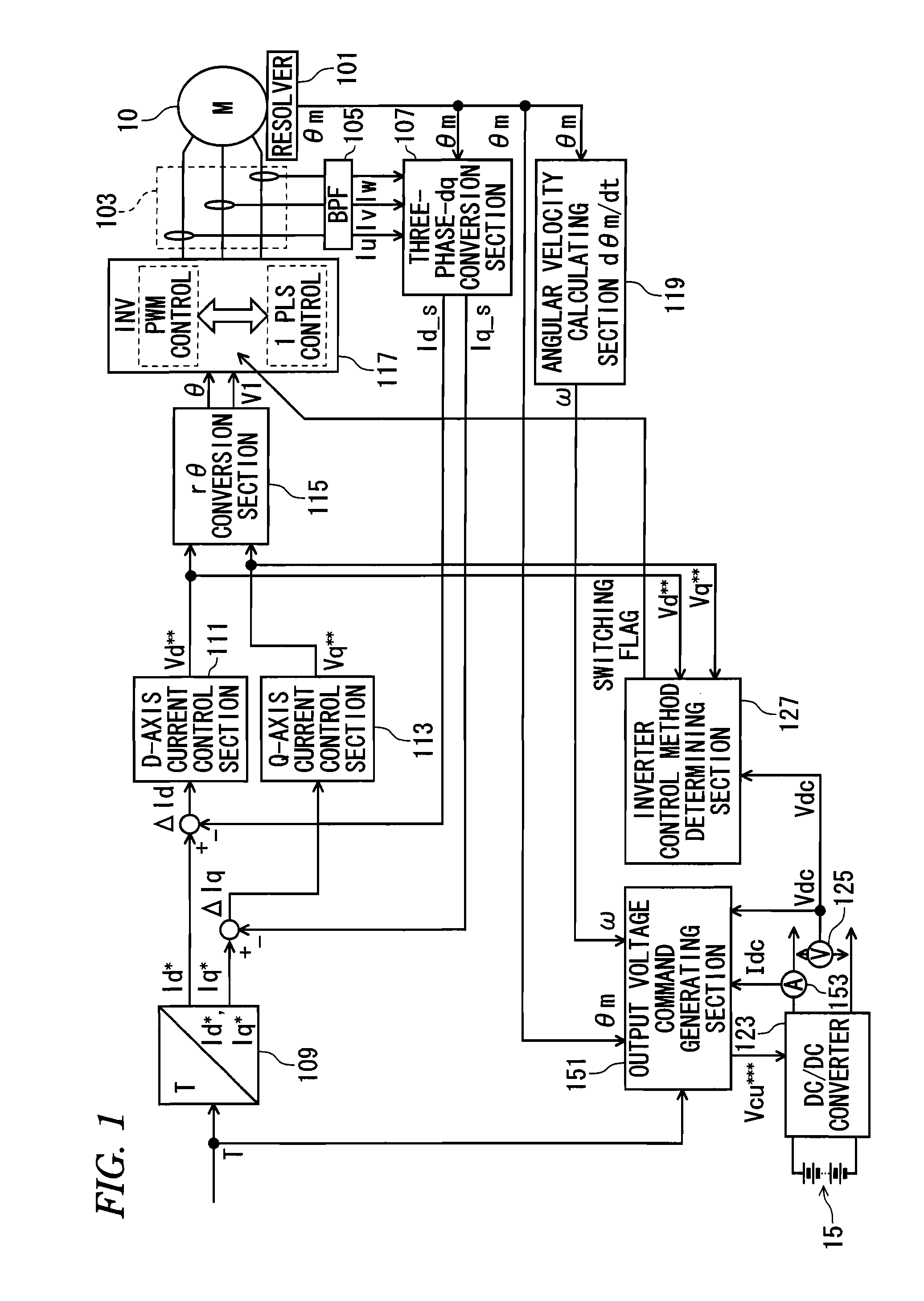
[0049]FIG. 1 is a block diagram showing a control apparatus for an electric motor according to a first embodiment. As shown in FIG. 1, similarly to the control apparatus for the electric motor shown in FIG. 18, the control apparatus for the electric motor according to the first embodiment has a resolver 101, a current sensor 103, a band pass filter (BPF) 105, a three-phase-dq conversion section 107, a current command calculating section 109, a d-axis current control section 111, a q-axis current control section 113, an rθconversion section 115, an inverter (INV) 117, an angular velocity calculating section 119, a DC-DC converter 123, an output voltage detecting section 125, and an inverter control method determining section 127, as well as an output voltage command generating section 151 serving as a replacement of the direct voltage command generating section 121. The control apparatus for the electric motor further has an output current detecting section 15...

second embodiment

[0062](Second Embodiment)

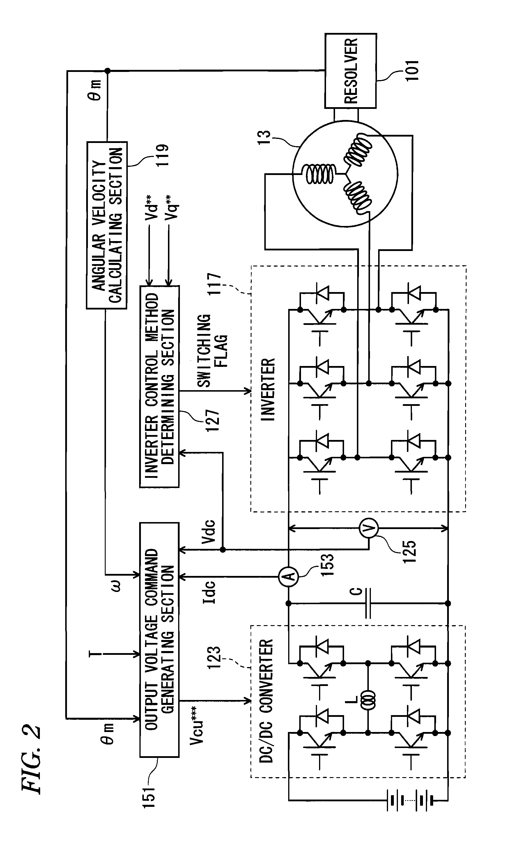
[0063]FIG. 10 is a block diagram showing a control apparatus for an electric motor according to a second embodiment. As shown in FIG. 10, in addition to the components provided in the control apparatus for the electric motor according to the first embodiment shown in FIG. 1, the control apparatus for the electric motor according to the second embodiment has a phase voltage detecting section 163 and a phase voltage cross point detecting section 165. Here, in FIG. 10, like components to those in FIG. 1 are designated by like reference numerals.

[0064]The phase voltage detecting section 163 detects three-phase alternating voltages Vu, Vv, and Vw applied onto a stator 13 of the electric motor 10. The three-phase alternating voltages Vu, Vv, and Vw detected by the phase voltage detecting section 163 are inputted to the phase voltage cross point detecting section 165. The phase voltage cross point detecting section 165 detects a timing that any two phase voltages a...

third embodiment

[0070](Third Embodiment)

[0071]FIG. 12 is a block diagram showing a control apparatus for an electric motor according to a third embodiment. As shown in FIG. 12, the control apparatus for the electric motor according to the third embodiment has a phase estimation section 173 in place of the resolver 101 provided in the control apparatus for the electric motor according to the first embodiment shown in FIG. 1. Here, in FIG. 12, like components to those in FIG. 1 are designated by like reference numerals.

[0072]The phase estimation section 173 estimates the electrical angle of the rotator of the electric motor 10 based on the three-phase alternating currents Iu, Iv, and Iw detected by the current sensor 103. The electrical angle θs estimated by the phase estimation section 173 is transmitted to the three-phase-dq conversion section 107, the angular velocity calculating section 119, and the output voltage command generating section 171. As such, the output voltage command generating sect...


PUM


Abstract

A control apparatus for an electric motor provided with a rotator having a permanent magnet and with a stator for generating a rotating magnetic field by an applied voltage and revolving the rotator includes: a rectangular wave inverter that applies a rectangular wave voltage onto the stator of the electric motor to drive the electric motor; a voltage converting section that raises or lowers an output voltage of a direct-current power supply and applies the voltage onto the rectangular wave inverter; an electrical angle acquiring section that acquires an electrical angle of the rotator of the electric motor; and an output voltage command generating section that generates a command for instructing the voltage converting section to output an electrical-angle synchronized voltage whose amplitude ripples in synchronization with a change of the electrical angle of the rotator acquired by the electrical angle acquiring section. In response to the command generated by the output voltage command generating section, the voltage converting section raises or lowers the output voltage of the direct-current power supply to a voltage indicated by the command and applies the voltage onto the rectangular wave inverter. This reduces a loss caused by a response delay of the electric motor.

Description

TECHNICAL FIELD[0001]The present invention relates to a control apparatus for an electric motor provided with a rotator having a permanent magnet and with a stator for generating a rotating magnetic field by an applied voltage and revolving the rotator.BACKGROUND ART[0002]FIG. 18 is a block diagram showing a control apparatus for an electric motor according to related art to the present invention. The control apparatus for the electric motor 10 shown in FIG. 18 has a resolver 101, a current sensor 103, a band pass filter (BPF) 105, a three-phase-dq conversion section 107, a current command calculating section 109, a d-axis current control section 111, a q-axis current control section 113, an rθ conversion section 115, an inverter (INV) 117, an angular velocity calculating section 119, a direct voltage command generating section 121, a DC-DC converter 123, an output voltage detecting section 125, and an inverter control method determining section 127. In the electric motor 10 shown i...

Claims


Application Information

Patent Timeline
Patent Type & Authority Patents(United States)
IPC IPC(8): H02P27/04H02P6/00H02P1/00H02P27/00H02P21/00H02P21/06H02P21/22H02P23/16H02P27/06H02P27/08
CPCH02P27/06
Inventor ATARASHI, HIROFUMIHORIKAWA, HITOSHINISHIDA, TOSHIYUKIKITA, MASATO
Owner HONDA MOTOR CO LTD
Why Eureka
Try Eureka