
Touch screen panel for display device

a display device and touch screen technology, applied in the field of touch screen panel for display device, can solve the problems of degrading touch performance, difficult to sense the touch position, difficult to easily handle products, etc., and achieve the effect of reducing the size of parasitic capacitance and improving touch performan

Active Publication Date: 2014-03-13
LG DISPLAY CO LTD
View PDF7 Cites 41 Cited by
  • Summary
  • Abstract
  • Description
  • Claims
  • Application Information

AI Technical Summary

Benefits of technology

The present invention is about a touch screen panel for a display device that can improve touch performance by reducing a type of unwanted electricity between first and second routing wires. The technical effect is that this innovation can make the touch screen more precise and reliable.

Problems solved by technology

However, the user has to learn how to use the input devices and the input device occupies a separate space, thus making it difficult to easily handle the products.
Furthermore, it is difficult to sense the touch position if the user touches the touch screen panel lightly.
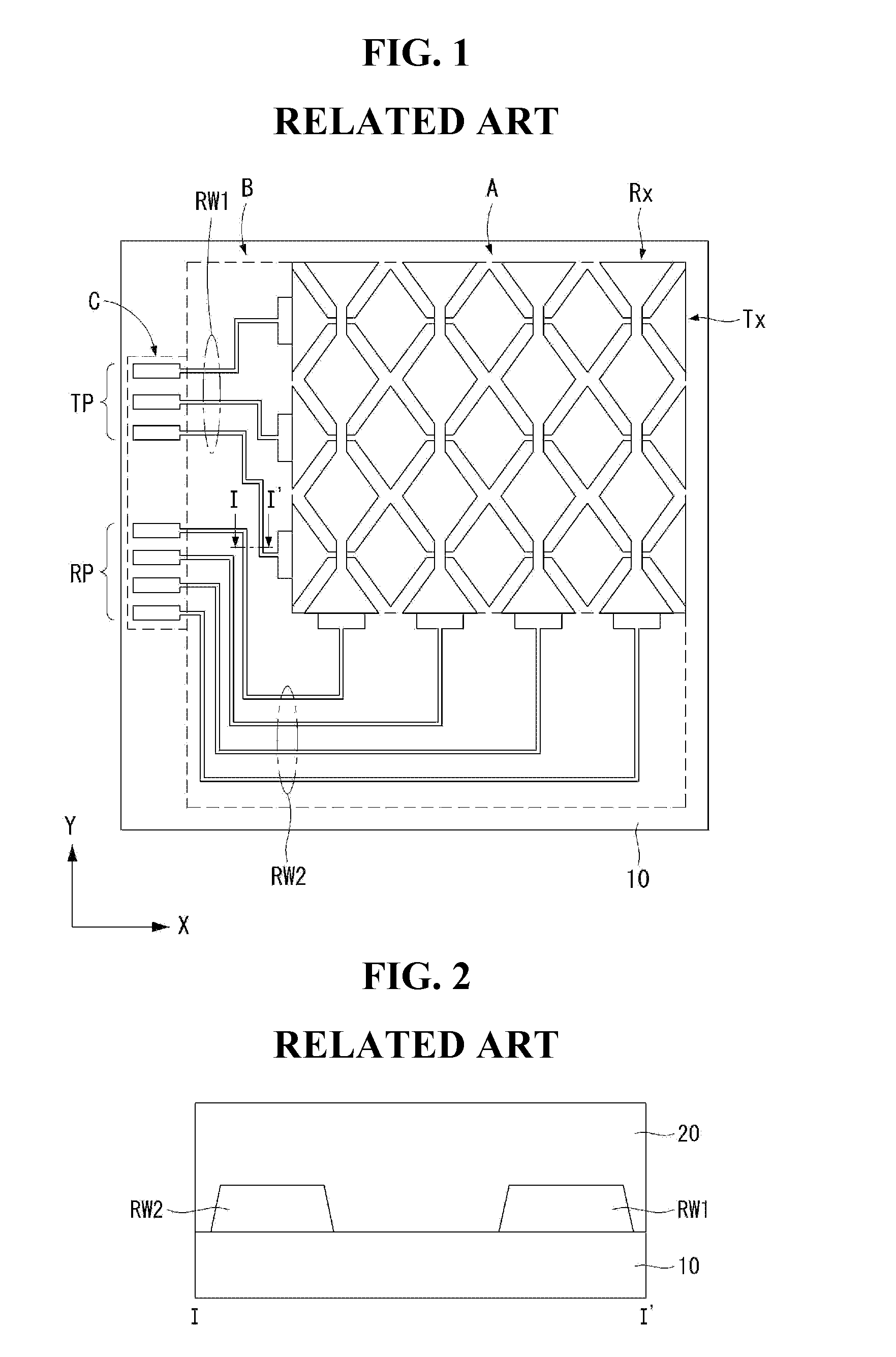
Thus, the parasitic capacitance between them increases the noise of the touch screen panel, thus degrading touch performance.
Although the distance between the first routing wires and the second routing wires can be increased to reduce the size of the parasitic capacitance, the effect of this method is not great, and bezel size is increased, thus leading to another problem of a smaller touch area.

Method used


Image

  • Touch screen panel for display device
  • Touch screen panel for display device
  • Touch screen panel for display device

Examples


Embodiment Construction

[0036]Hereinafter, exemplary embodiments of the present invention will be described in detail with reference to the accompanying drawings. Like reference numerals designate substantially like elements throughout the specification. Herein a terminology “electrode string” means that a plurality of electrodes having a predetermined shape are connected in line.

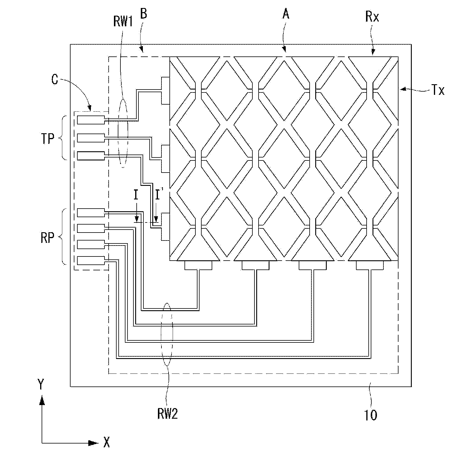
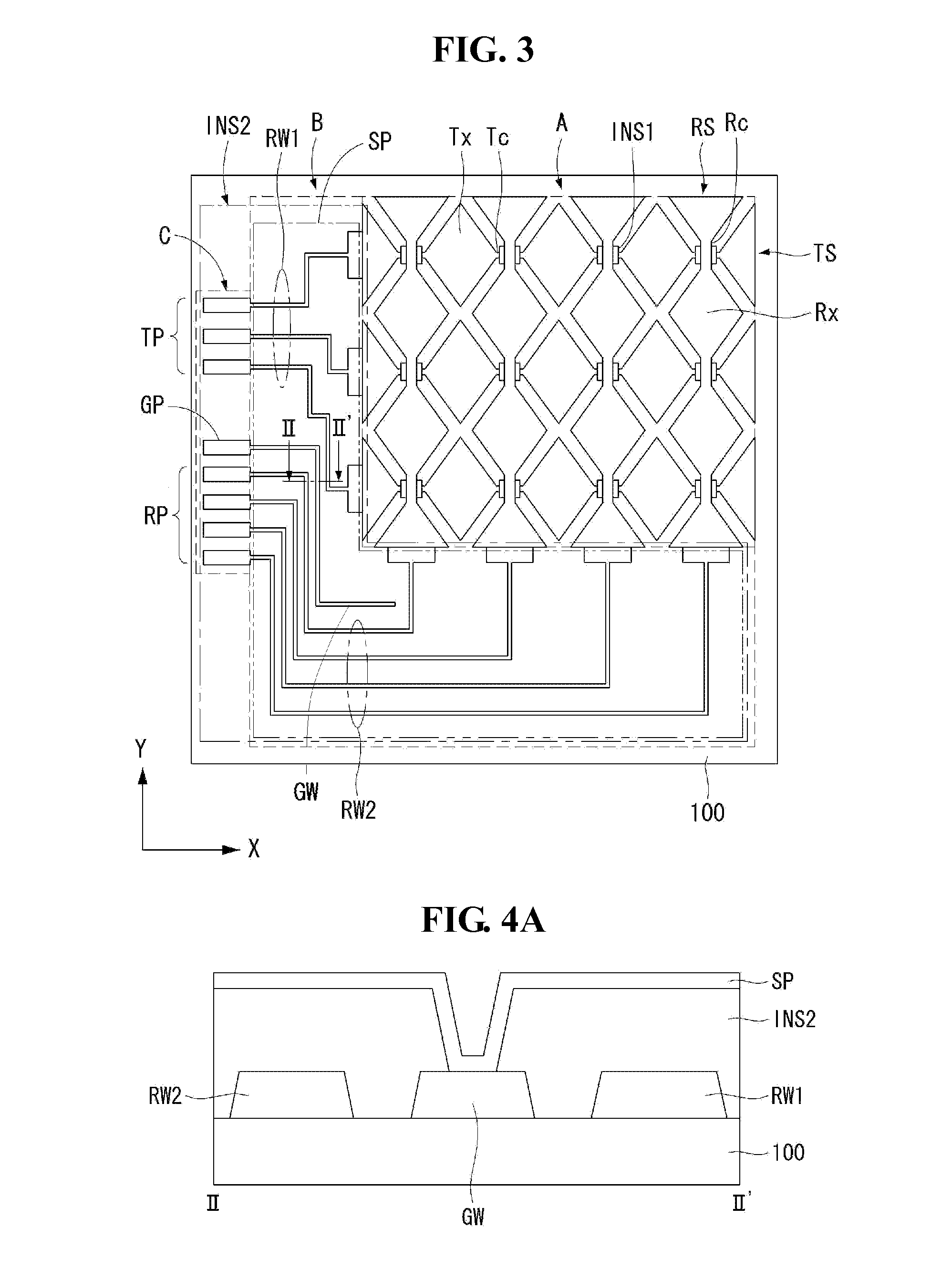
[0037]First of all, a touch screen panel according to exemplary embodiments of the present invention will be described with reference to FIG. 3 and FIGS. 4A to 4C. FIG. 3 is a top plan view of a touch screen panel according to an exemplary embodiment of the present invention. FIGS. 4A to 4C are cross-sectional views taken along line II-II′ of FIG. 3, illustrating other examples of the position where a shield pattern is formed.

[0038]Referring to FIG. 3 and FIGS. 4A to 4C, the touch screen panel includes a touch area A where a touch occurs, a routing wire area B, and a pad area C.

[0039]The touch area A includes a plurality of first ...


PUM


Abstract

This disclosure relates to a touch screen panel for a display device. The touch screen panel includes a base layer, a plurality of first electrode strings, a plurality of second electrode strings, a plurality of first routing wires, a plurality of second routing wires; a third wire formed between the first routing wires and the second routing wires, an insulation layer that covers the first and second routing wires and the third wires and has contact holes exposing a part of the third wire, and a shield pattern that is formed on the insulation layer contacts the third wires through the contact holes, and overlaps either the first routing wires or the second routing wires.

Description

[0001]This application claims priority under 35 U.S.C. §119(a) to Korean Patent Application No. 10-2012-0100260 filed on Sep. 11, 2012, which is hereby incorporated by reference in its entirety.BACKGROUND[0002]1. Field[0003]This document relates to a touch screen panel for a display device, and more particularly, to a touch screen panel for a display device capable of improving touch sensitivity.[0004]2. Related Art[0005]Various input devices, such as a keyboard, a mouse, a trackball, a joystick, a digitizer, and the like, are used to configure an interface between a user and home appliances or various information communication devices. However, the user has to learn how to use the input devices and the input device occupies a separate space, thus making it difficult to easily handle the products. Thus, a demand for simple and convenient input devices capable of reducing malfunction has been increasing day by day. A touch screen panel, through which the user inputs information by di...

Claims


Application Information

Patent Timeline
Patent Type & Authority Applications(United States)
IPC IPC(8): G06F3/041
CPCG06F3/041G06F2203/04107G06F2203/04111G06F3/0443G06F3/0446G06F3/044
Inventor CHO, SUNGYONG
Owner LG DISPLAY CO LTD
Learn More