
Apparatus and method for determining optical center in camera module

a technology of optical center and camera module, which is applied in the field of apparatus and method for determining optical center in camera module, can solve the problem of setting a threshold and generate a large deviation, and achieve the effect of accurate optical center, accurate measurement of optical center, and reduction of camera module defect ra

Active Publication Date: 2014-03-13
LG INNOTEK CO LTD
View PDF2 Cites 2 Cited by
  • Summary
  • Abstract
  • Description
  • Claims
  • Application Information

AI Technical Summary

Benefits of technology

The present patent is about an apparatus and method for accurately determining the optical center of a camera module, which helps reduce defects in the camera module caused by measurement errors. It also allows for a more precise measurement of the influence of the lens on the optical performance of the camera module in case of any problem with the optical performance.

Problems solved by technology

The optical center was conventionally measured by using a method of obtaining a centroid relative to a round range having a threshold in an image, but this method suffers from disadvantages in that it is seriously affected by an image noise and evenness of lens shading.
This method also suffers from disadvantages in that a great deviation is generated by setting of a threshold, because the shading itself is widely spread, and a measurement subject takes only a portion having the same threshold.

Method used


Image

  • Apparatus and method for determining optical center in camera module
  • Apparatus and method for determining optical center in camera module
  • Apparatus and method for determining optical center in camera module

Examples


Embodiment Construction

[0029]Advantages and features of the present disclosure may be understood more readily by reference to the following detailed description of exemplary embodiments and the accompanying drawings. Thus, the present disclosure is not limited to the exemplary embodiments which will be described below, but may be implemented in other forms. Accordingly, the described aspect is intended to embrace all such alterations, modifications, and variations that fall within the scope and novel idea of the present disclosure.

[0030]Now, exemplary embodiments of the present disclosure will be described in detail with reference to the accompanying drawings.

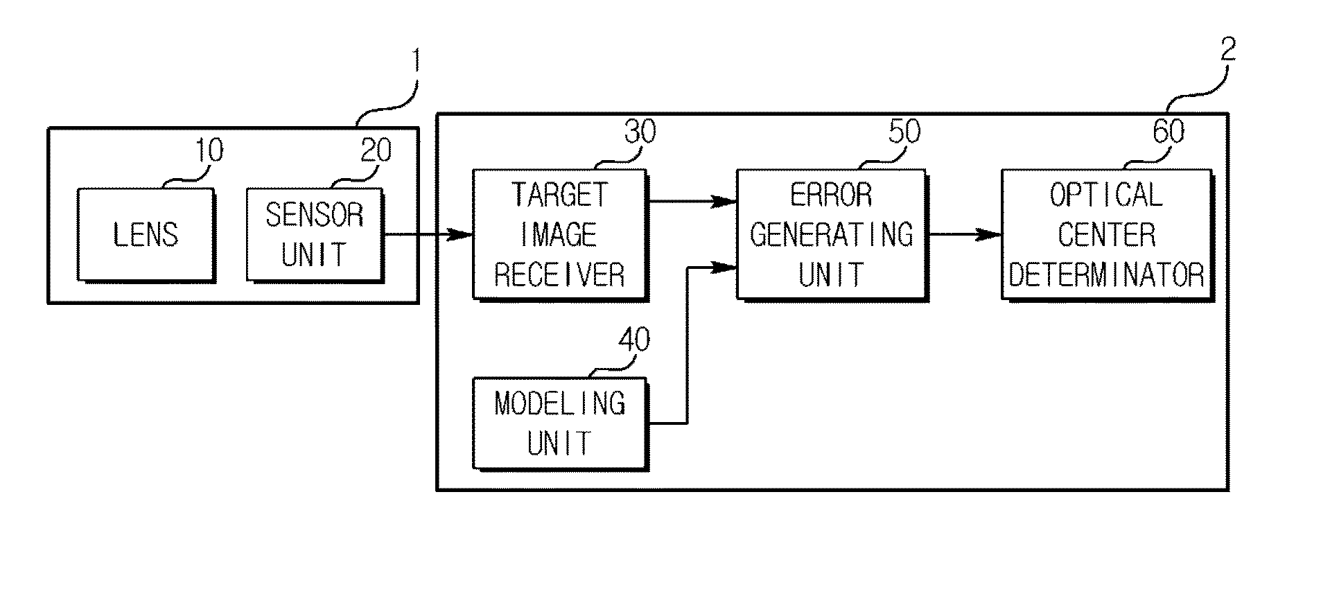
[0031]FIG. 1 is a block diagram illustrating an apparatus for determining an optical center in a camera module according to an exemplary embodiment of the present disclosure.

[0032]Referring to FIG. 1, the apparatus (2) for determining an optical center in a camera module according to an exemplary embodiment of the present disclosure (hereinafter refe...


PUM


Abstract

An apparatus and method for determining optical center in camera module are provided, the method for determining optical center in camera module according to an exemplary embodiment comprising receiving a target image from a camera module including a lens; generating an error data, which is a difference between a pixel value of the target image and a pixel value of a Gaussian distribution image; and determining the optical center of the lens based on the error data.

Description

CROSS-REFERENCE TO RELATED APPLICATION[0001]The present application is based on, and claim priority from, Korean Application Numbers 10-2012-0101759, filed on Sep. 13, 2012, the disclosures of which is incorporated by reference herein in its entirety.BACKGROUND OF THE INVENTION[0002]1. Field of the Invention[0003]Exemplary aspects of the present disclosure relate to an apparatus and method for determining optical center in camera module.[0004]2. Description of Related Art[0005]In general, a position of a lens on which an image is captured in a sensor of a camera module is called an optical center. The optical center was conventionally measured by using a method of obtaining a centroid relative to a round range having a threshold in an image, but this method suffers from disadvantages in that it is seriously affected by an image noise and evenness of lens shading.[0006]This method also suffers from disadvantages in that a great deviation is generated by setting of a threshold, becaus...

Claims


Application Information

Patent Timeline
Patent Type & Authority Applications(United States)
IPC IPC(8): G01M11/02
CPCG01M11/0221H04N17/00H04N23/81H04N23/00
Inventor PARK, SEJIN
Owner LG INNOTEK CO LTD
Features
  • Generate Ideas
  • Intellectual Property
  • Life Sciences
  • Materials
  • Tech Scout
  • Unparalleled Data Quality
  • Higher Quality Content
  • 60% Fewer Hallucinations
Learn More