
Intensifier Pump Monitoring System

Inactive Publication Date: 2014-03-13
HYPERTHERM INC
View PDF1 Cites 7 Cited by
  • Summary
  • Abstract
  • Description
  • Claims
  • Application Information

AI Technical Summary

Benefits of technology

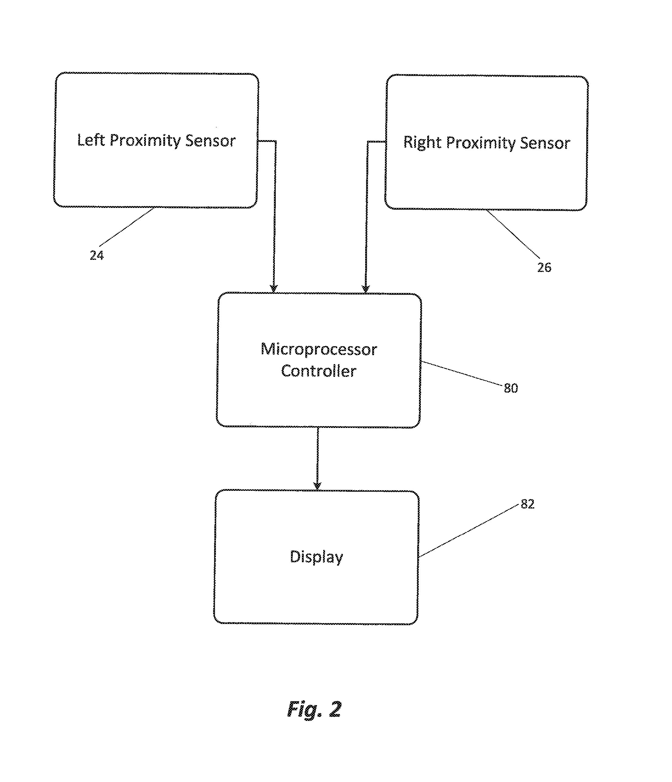
The patent describes a method and device for displaying the performance of an intensifier pump used for water-jet cutting. The device uses sensors to measure the timing of plunger movements and a microprocessor to analyze and display the results on a panel. This allows for quick identification of any problems with the pump's performance. Overall, the device helps improve the efficiency and reliability of the intensifier pump.

Problems solved by technology

More particularly, the graphics display presents side-by-side bars whose height and color reflect proper operation, limited but still acceptable operation, and an alarm or shutdown state of the intensifier pump assembly.

Method used


Image

  • Intensifier Pump Monitoring System
  • Intensifier Pump Monitoring System
  • Intensifier Pump Monitoring System

Examples


Embodiment Construction

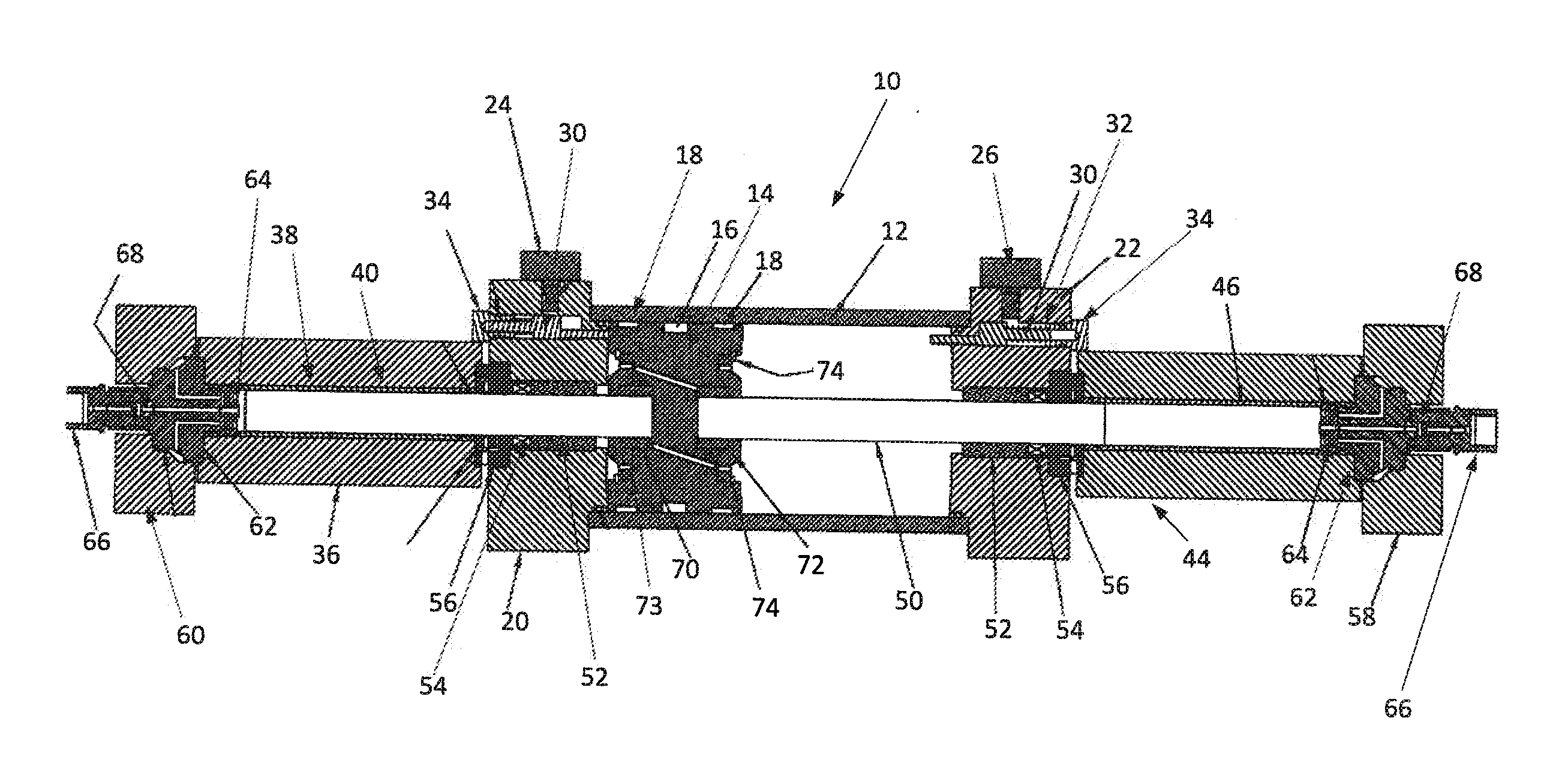
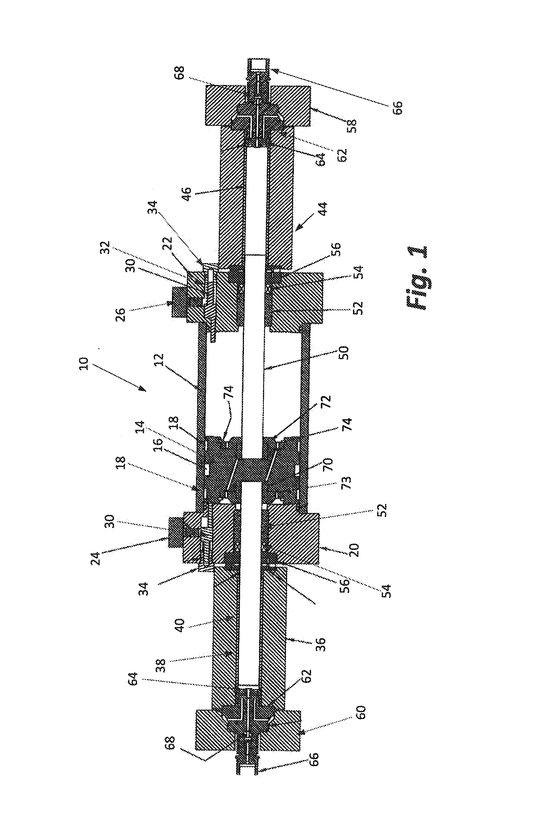
[0016]This description of the preferred embodiments is intended to be read in connection with the accompanying drawings, which are to be considered part of the entire written description of this invention. In the description, relative terms such as “lower”, “upper”, “horizontal”, “vertical”, “above”, “below”, “right”, “left”, “top” and “bottom” as well as derivatives thereof (e.g., “horizontally”, “downwardly”, “upwardly”, etc.) should be construed to refer to the orientation as then described or as shown in the drawings under discussion. These relative terms are for convenience of description and do not require that the apparatus be constructed or operated in a particular orientation. Terms such as “connected”, “connecting”, “attached”, “attaching”, “join” and “joining” are used interchangeably and refer to one structure or surface being secured to another structure or surface or integrally fabricated in one piece, unless expressively described otherwise.

[0017]Furthermore, and as u...


PUM


Abstract

An apparatus and method of graphically indicating the performance of intensifier pumps used in water-jet cutting utilizes output signals from end-of-stroke proximity sensors to establish stroke times for the pump's plungers. The stroke times are then used to present bar graphs for each plunger reflecting the magnitude of the time valve by the height of the bars and performance status by the color of the bars.

Description

BACKGROUND OF THE INVENTION[0001]I. Field of the Invention[0002]This invention relates generally to water-jet cutting systems, and more particularly to a method and apparatus for monitoring the performance of intensifier pumps commonly employed in such water-jet cutting systems.[0003]II. Discussion of the Prior Art[0004]As is now well-known in the art, a water-jet cutter comprises a tool capable of slicing through a variety of materials using a jet of water at high velocity and pressure. Water-jet cutters are frequently used in the manufacture of machinery parts, fabrication of stone countertops and especially in applications where parts forming operations must be performed at lower temperatures than can be achieved using more conventional machining operations.[0005]In water-jet cutters, a so-called intensifier pump or some other technology for creating high pressure is coupled to a cutting head having an outlet orifice less than one millimeter in diameter and the intensifier pump m...

Claims


Application Information

Patent Timeline
IPC IPC(8): F04B49/00
CPCB26D5/00B26F3/004F04B9/113F04B49/065F04B2203/0903
Inventor VANDERGON, CEDAR J.CHALMERS, ERIC J.
Owner HYPERTHERM INC
Learn More