Magnetic resonance image recording unit and a magnetic resonance device having the magnetic resonance image recording unit

a magnetic resonance image and recording unit technology, applied in diagnostic recording/measuring, instruments, applications, etc., can solve the problems of increasing the workload of operating personnel, affecting the accuracy of the magnetic resonance measurement, and reducing the informative significan

Inactive Publication Date: 2014-03-13
SIEMENS AG
View PDF10 Cites 43 Cited by
  • Summary
  • Abstract
  • Description
  • Claims
  • Application Information

AI Technical Summary

Benefits of technology

[0009]It is proposed that the motion sensor unit has at least one motion sensor element which is arranged in a section of a side of the first housing wall facing away from the patient receiving area, as a result of which the motion sensor unit, in particular the at least one motion sensor element of the motion sensor unit, can be integrated in a particularly space-saving and constructionally simple manner within the magnetic resonance image recording unit. Moreover, this enables an in particular spatial encroachment on the patient inside the patient receiving area due to the motion sensor unit to be advantageously prevented.
[0025]It can furthermore be provided that the patient positioning device includes the magnetic resonance image recording unit, thereby advantageously enabling any movement of the patient positioned on the patient positioning device to be detected.

Problems solved by technology

Movements of the patient during the magnetic resonance measurement can produce artifacts in the magnetic resonance images which subsequently, during a medical assessment of the magnetic resonance images, can lead to a misinterpretation and / or a reduction in informative significance.
In particular in the case of magnetic resonance measurements of claustrophobically inclined patients and / or pain patients and / or children, it is often difficult for the patient to remain lying motionless for the duration of the magnetic resonance measurement.
Thus, for example, in http: / / www.eng.hawaii.edu / college-events / 2012-events / Ernst-MRImotionCorrection.pdf a method is disclosed in which additional marker elements are positioned on the patient, although this can lead to an increased workload for operating personnel.
However, this method can be implemented only with difficulty due to a constriction in for example a head coil unit.
Furthermore, this method has only insufficient precision in detecting the motion.

Method used


Image

  • Magnetic resonance image recording unit and a magnetic resonance device having the magnetic resonance image recording unit
  • Magnetic resonance image recording unit and a magnetic resonance device having the magnetic resonance image recording unit
  • Magnetic resonance image recording unit and a magnetic resonance device having the magnetic resonance image recording unit

Examples


Embodiment Construction

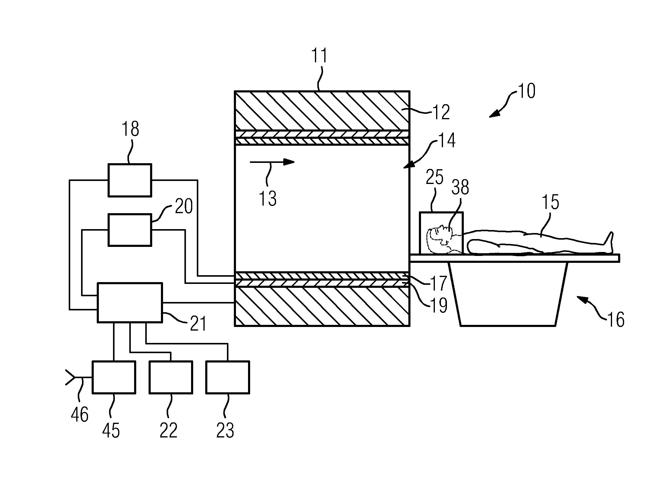
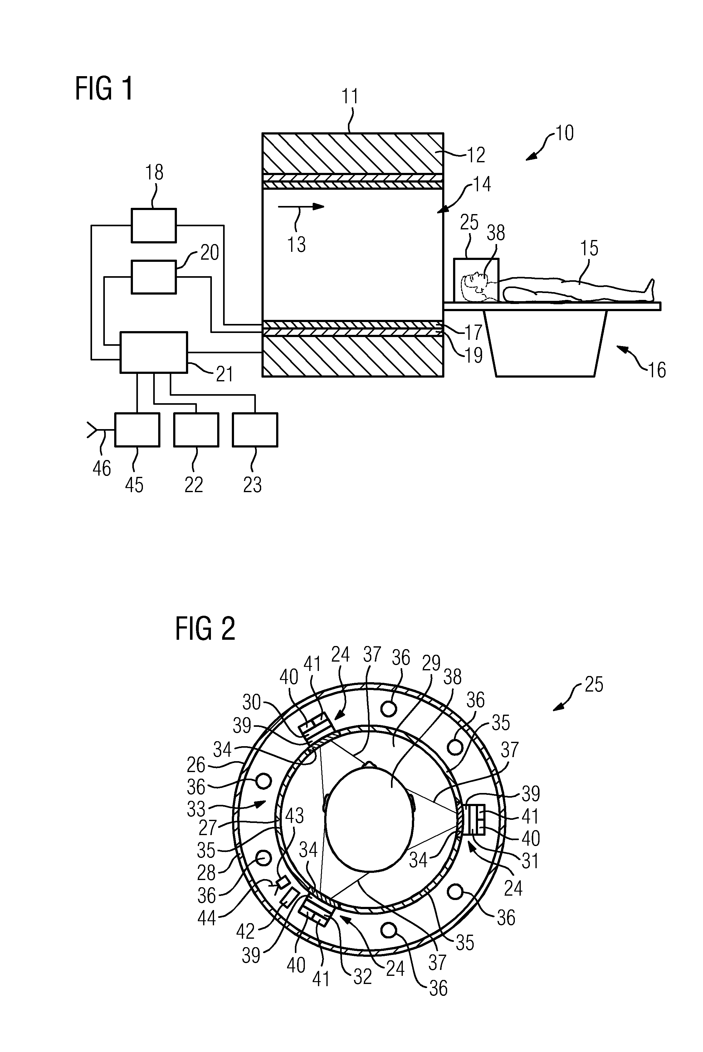
[0031]A magnetic resonance device 10 according to the invention is shown in FIG. 1. The magnetic resonance device 10 comprises a magnet unit 11 having a main magnet 12 for generating a strong, and in particular constant, main magnetic field 13. In addition, the magnetic resonance device 10 has a cylinder-shaped patient receiving area 14 for accommodating a patient 15, the patient receiving area 14 being enclosed by the magnet unit 11 in a circumferential direction. The patient 15 can be introduced into the patient receiving area 14 by means of a patient positioning device 16 of the magnetic resonance device 10.

[0032]The magnet unit 11 also has a gradient coil unit 17 for generating magnetic field gradients that are used for spatial encoding during an imaging session. The gradient coil unit 17 is controlled by way of a gradient control unit 18. In addition, the magnet unit 11 has a radio-frequency antenna unit 19 permanently integrated within the magnet unit 11 and a radio-frequency ...


PUM


Abstract

A magnetic resonance image recording unit for recording at least part of a patient during a magnetic resonance examination is presented. The magnetic resonance image recording unit has a first housing wall, a patient receiving area which is at least partially enclosed by the first housing wall, and a motion sensor unit for detecting a movement of the patient. The motion sensor unit has at least one motion sensor element which is arranged in a section of a side of the first housing wall facing away from the patient receiving area.

Description

CROSS REFERENCE TO RELATED APPLICATIONS[0001]This application claims priority to German application No. 10 2012 216 303.4 DE filed Sep. 13, 2012, the entire content of which is hereby incorporated herein by reference.FIELD OF INVENTION[0002]The present invention relates to a magnetic resonance image recording unit for recording at least part of a patient during a magnetic resonance examination, the magnetic resonance image recording unit having a first housing wall, a patient receiving area which is at least partially enclosed by the first housing wall, and a motion sensor unit for detecting a movement of the patient.BACKGROUND OF INVENTION[0003]For magnetic resonance imaging it is important that a patient executes no movements for the entire duration of the magnetic resonance measurement. Movements of the patient during the magnetic resonance measurement can produce artifacts in the magnetic resonance images which subsequently, during a medical assessment of the magnetic resonance ...

Claims


Application Information

Patent Timeline
Patent Type & Authority Applications(United States)
IPC IPC(8): G01R33/563
CPCG01R33/56308G01R33/28G01R33/56509
Inventor BIBER, STEPHAN
Owner SIEMENS AG
Why Eureka
Try Eureka