Working tower, rod inserter, rod reducer, and compression-distraction tool for minimally invasive surgery system

a technology of minimally invasive surgery and working tower, which is applied in the field of working tower, reducer, and compression-distraction tool for minimally invasive surgery system, can solve the problems of low satisfaction, damaged disc between vertebrae, slow recovery, etc., and achieves simple structure, convenient use of working tower, and easy mounting and removal.

Inactive Publication Date: 2014-03-13
GS MEDICAL CO LTD
View PDF0 Cites 66 Cited by
  • Summary
  • Abstract
  • Description
  • Claims
  • Application Information

AI Technical Summary

Benefits of technology

[0025]In one embodiment, a compression-distraction tool for spreading a first and a second correction screws on lower ends of a first and a second working towers from each other in a distraction mode, or approaching the first and second correction screws to each other in a compression mode in a minimally invasive surgery, is provided, which may include a pivot positioned between the first and second working towers, a tower compressing unit provided on one end of the pivot to compress the first and second working towers so that the first and second working towers are tilt with reference to the pivot, and a tower supporter rotatably provided on the other end of the pivot to prevent movement of the first and second working towers in a lengthwise direction of the pivot.
[0026]According to the first embodiment of the invention, it is easy to use the working tower because, compared to the conventional rod guide, a correction screw is easily mountable and removable without requiring a use of a separate separator.
[0027]According to the second embodiment of the invention, a rod inserter with simpler structure and easier operation than the conventional rod holder is provided.
[0028]According to the third embodiment of the invention, compared to the conventional rod pusher, the rod reducer can prevent a possibility that tissues are caught in between the rod and the set screw thanks to a structure which enables to press the rod and at the same time coupled the set screw to the correction screw, and can also minimize interference with the adjacent members thanks to a structure thereof which is insertable into another member.
[0029]According to the fourth embodiment of the invention, compared to the conventional space adjusting tool, the compression-distraction tool can provide a wide range of displacement adjustment for distraction and compression between the correction screws, and can also prevent the possibility that a member positioned on a pivot is moved in a lengthwise direction of the pivot.

Problems solved by technology

Due to the structure of the spine, disc between vertebrae is damaged when exposed to incorrect posture for a prolonged time, or due to age-related degenerative diseases or external shock, and intervertebral disc disease may develop.
However, considering the downside of the above-mentioned surgery, that is, slow recovery due to relatively large invasive area, and low satisfaction due to wounds after surgery, minimally invasive surgery has been developed.
That is, the practitioner has to force-fit the pedicle screw 10 into the gripping portion 61b which can be cumbersome.
Further, structure is complex due to a need for a separate rod guide separator (not illustrated) to efficiently separate the force-fit pedicle screw 10 from the gripping part 61b of the rod guide 60 after surgery.
Furthermore, because the conventional rod holder 30 is designed to be loaded with rod by two steps, it has complicated structure.
Use of the conventional rod holder 30 is also inconvenient because it is necessary to separately manipulate a button portion 37 in addition to the manipulation to lift up or lower down the loading portion 35.
Also, the present inventive concept is not required to overcome the disadvantages described above, and an exemplary embodiment of the present inventive concept may not overcome any of the problems described above.

Method used


Image

  • Working tower, rod inserter, rod reducer, and compression-distraction tool for minimally invasive surgery system
  • Working tower, rod inserter, rod reducer, and compression-distraction tool for minimally invasive surgery system
  • Working tower, rod inserter, rod reducer, and compression-distraction tool for minimally invasive surgery system

Examples


first embodiment

[0069]FIG. 2 is a perspective view of a working tower according to the invention, FIG. 3 is a cross-section view illustrating the working tower of FIG. 2 which has branched-apart portions, and FIG. 4 is a longitudinal cross-section illustrating the gripping portion inserted in the state of FIG. 3.

[0070]FIG. 5 is a cross-section view illustrating interior of an exterior pipe of the working tower of FIG. 2, and FIG. 6 is a cross section view taken on line VI-VI of the working tower of FIG. 3.

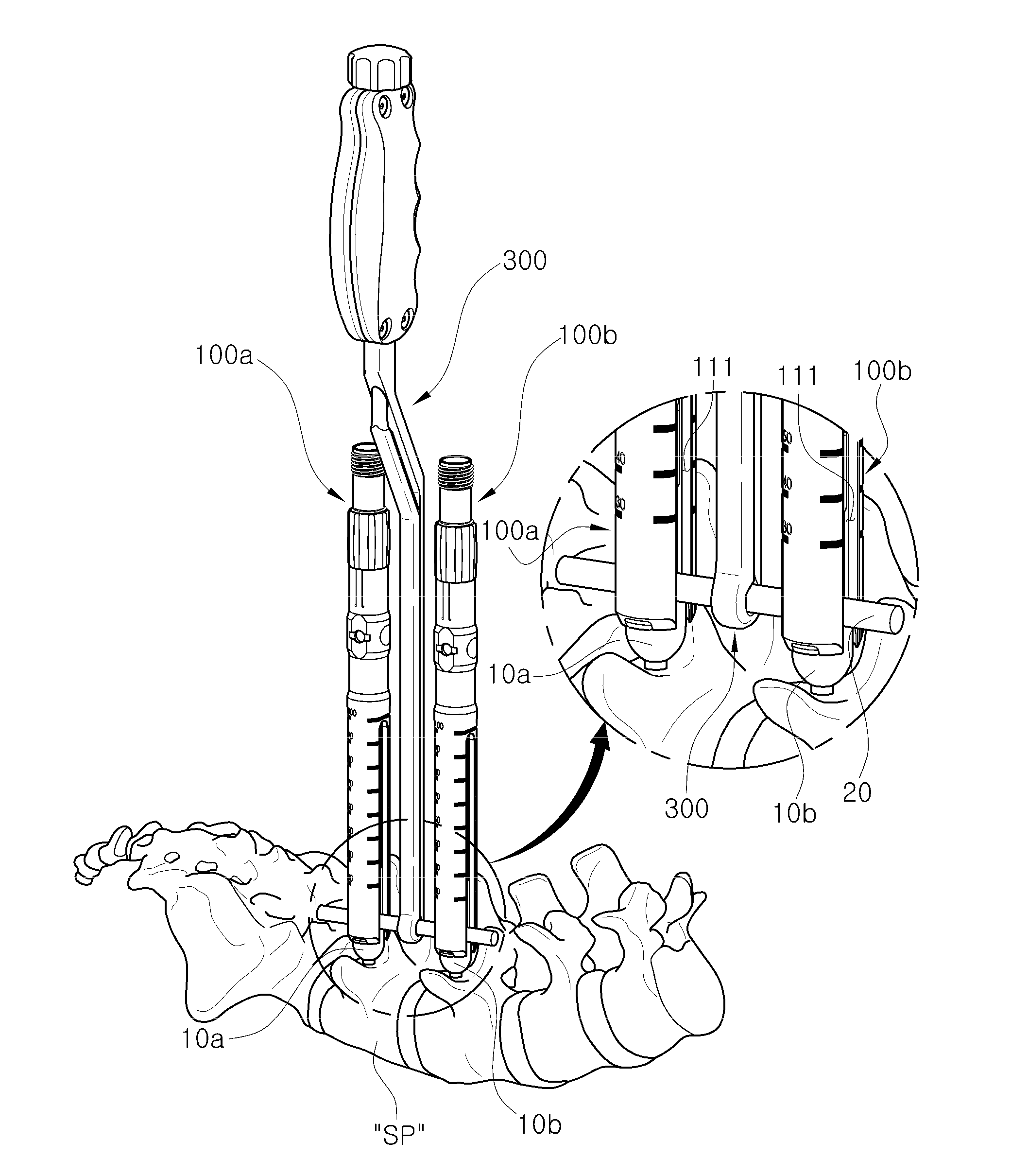
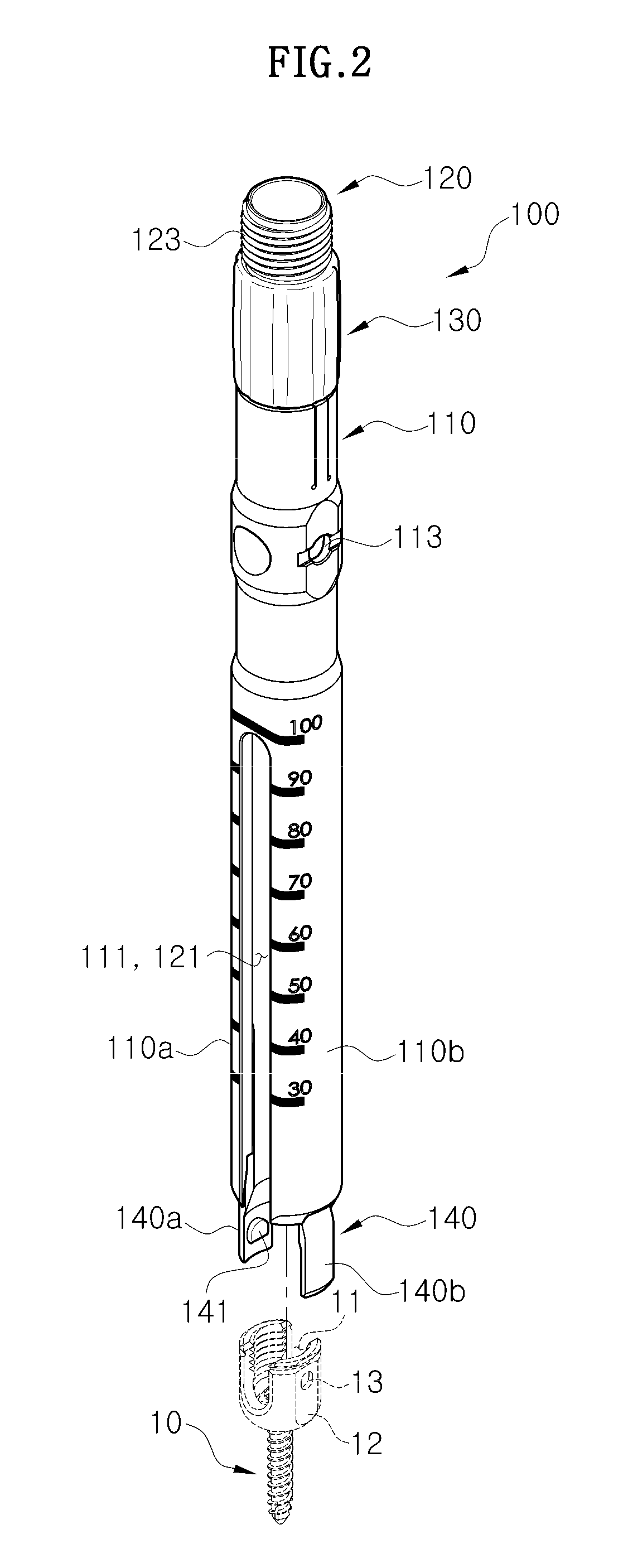
[0071]Referring to FIGS. 2 to 4, according to a first embodiment of the invention, the working tower 100 grips a correction screw 10, and plays a role of a working surface of the other external devices such as, for example, rod inserter 300, 500 (FIGS. 7, 20), rod reducer 700 (FIG. 27), or compression-distraction tool 900 (FIG. 31). The working tower 100 includes an exterior pipe 110, an interior pipe 120, a driving sleeve 130, and a screw holder 140.

[0072]The exterior pipe 110 is a tubular member...

second embodiment

[0086]The rod inserter according to the invention will be explained in greater detail below with reference to FIGS. 7 to 12.

[0087]FIG. 7 is a perspective view of a rod inserter according to a second embodiment of the invention, FIG. 8 is a front view of the rod inserter of FIG. 7, and FIG. 9 is a cross section view taken on line IX-IX of the rod inserter of FIG. 8.

[0088]FIG. 10 is a plan view of encircled portion “A” of FIG. 8, FIG. 11 is a cross-section view taken on line XI-XI of the rod inserter of FIG. 8, and FIG. 12 is a cross-section view taken on line XII-XII of the rod inserter of FIG. 8.

[0089]According to the second embodiment of the invention, the rod inserter 300 grips the rod 20 and seats the rod 20 onto the rod accommodating part 11 of at least two correction screws 10. Referring to FIGS. 7 to 12, the rod inserter 300 includes a fixed bar 310, a moving bar 320, an adjusting knob 330, and a rod holder 340.

[0090]The fixed bar 310 is provided in the form of a bar which is ...

third embodiment

[0127]The rod reducer according to the invention will be explained below with reference to FIGS. 26 and 27.

[0128]FIG. 26 is a perspective view of a rod reducer according to a third embodiment of the invention, and FIG. 27 is a longitudinal cross-section view of the rod reducer of FIG. 26.

[0129]The rod reducer 700 according to the third embodiment of the invention presses the rod 20 (FIG. 28) seated on the rod accommodating part 11 (FIG. 28) of the correction screw 10 (FIG. 28) and at the same time couples a set screw S (FIG. 29) onto the rod accommodating part 11 (FIG. 29). Referring to FIGS. 26 and 27, the rod reducer 700 includes an exterior member 710, an interior member 720, a coupling sleeve 730, and a rotation handle 740.

[0130]The exterior member 710, provided in a tubular form, has a set screw mounting part 711 formed on a lower portion thereof to mount the set screw S (FIG. 28).

[0131]The interior member 720, provided in a rod-like form, is slidably formed inside the exterior...


PUM


Abstract

A working tower for gripping a correction screw during minimally invasive surgery and playing a role of a working surface for other external devices is provided, which includes an exterior pipe, an interior pipe slidably provided within the exterior pipe, a driving sleeve rotatably connected to the exterior pipe and screw-coupled to the interior pipe to move the interior pipe upward and downward along a lengthwise direction thereof during rotation, and a screw holder provided on a lower end of the interior pipe, and is elastically split apart to receive a head portion of the correction screw when withdrawn from the exterior pipe, and contracted to securely hold the head portion when inserted into the exterior pipe.

Description

CROSS-REFERENCE TO RELATED APPLICATIONS[0001]This application claims priority from Korean Patent Application No. 2012-0100966, filed on Sep. 12, 2012, in the Korean Intellectual Property Office, the disclosure of which is incorporated herein by reference in its entirety.BACKGROUND[0002]1. Field of the Invention[0003]The invention relates to a working tower, a rod inserter, a rod reducer, and a compression-distraction tool for a minimally invasive surgery system.[0004]2. Description of the Related Art[0005]Generally, vertebral column (spine) consists of 24 vertebrae (excluding sacrovertebra and caudal vertebra), and plays a role of supporting posture of a body and body movements, and importantly, protecting internal organs.[0006]There is intervertebral disc between vertebrae which works as a buffer to absorb shock exerted thereto. The spinal cord runs through the vertebrae of the spine.[0007]Due to the structure of the spine, disc between vertebrae is damaged when exposed to incorrec...

Claims


Application Information

Patent Timeline
Patent Type & Authority Applications(United States)
IPC IPC(8): A61B17/70
CPCA61B17/7079A61B17/708A61B17/7085A61B17/7086A61B17/70A61B17/86A61B17/88
Inventor SHIN, MIN-SIK
Owner GS MEDICAL CO LTD
Why Eureka
Try Eureka