Fixation Anchor Design for an Occlusion Device

Inactive Publication Date: 2014-03-13
BOSTON SCI SCIMED INC
View PDF6 Cites 55 Cited by
  • Summary
  • Abstract
  • Description
  • Claims
  • Application Information

AI Technical Summary

Benefits of technology

[0009]An implantable medical device having barbs that reduce in height and change angle as the implantable device transitions from an expanded state to a constrained state may lessen the risk of injury associated with the removal and/or repositioning of the deployed device. Such a medical device, implantable within and retrievable from the vasculature of a patient, may comprise a main body formed from a plurality of ribs extending radially outwards from a nexus that are capable of transitioning from an expanded state to a collapsed state. The plurality of ribs defines an interior of the main of the body. Within the main body may be positioned a plurality of fixation struts. When the main body is in the exp

Problems solved by technology

While the inclusion of barbs on an implantable medical device may be beneficial in reducing migration, they may also be burdensome when repositioning and/or removing the implantable medical device.
Moving the implantable medical device in the expanded state, however, may cause damage to the surrounding tissue as a consequence of barbs engaging the tissue.
Additionally, engagement of the surrounding tissue by barbs may cause c

Method used


Image

  • Fixation Anchor Design for an Occlusion Device
  • Fixation Anchor Design for an Occlusion Device
  • Fixation Anchor Design for an Occlusion Device

Examples


Embodiment Construction

[0031]While this invention may be embodied in many different forms, there are described in detail herein specific embodiments of the invention. This description is an exemplification of the principles of the invention and is not intended to limit the invention to the particular embodiments illustrated.

[0032]For the purposes of this disclosure, like reference numerals in the figures shall refer to like features unless otherwise indicated.

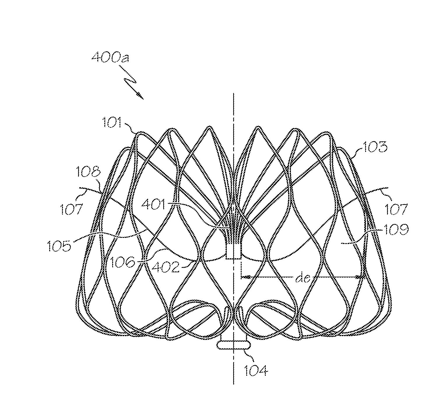
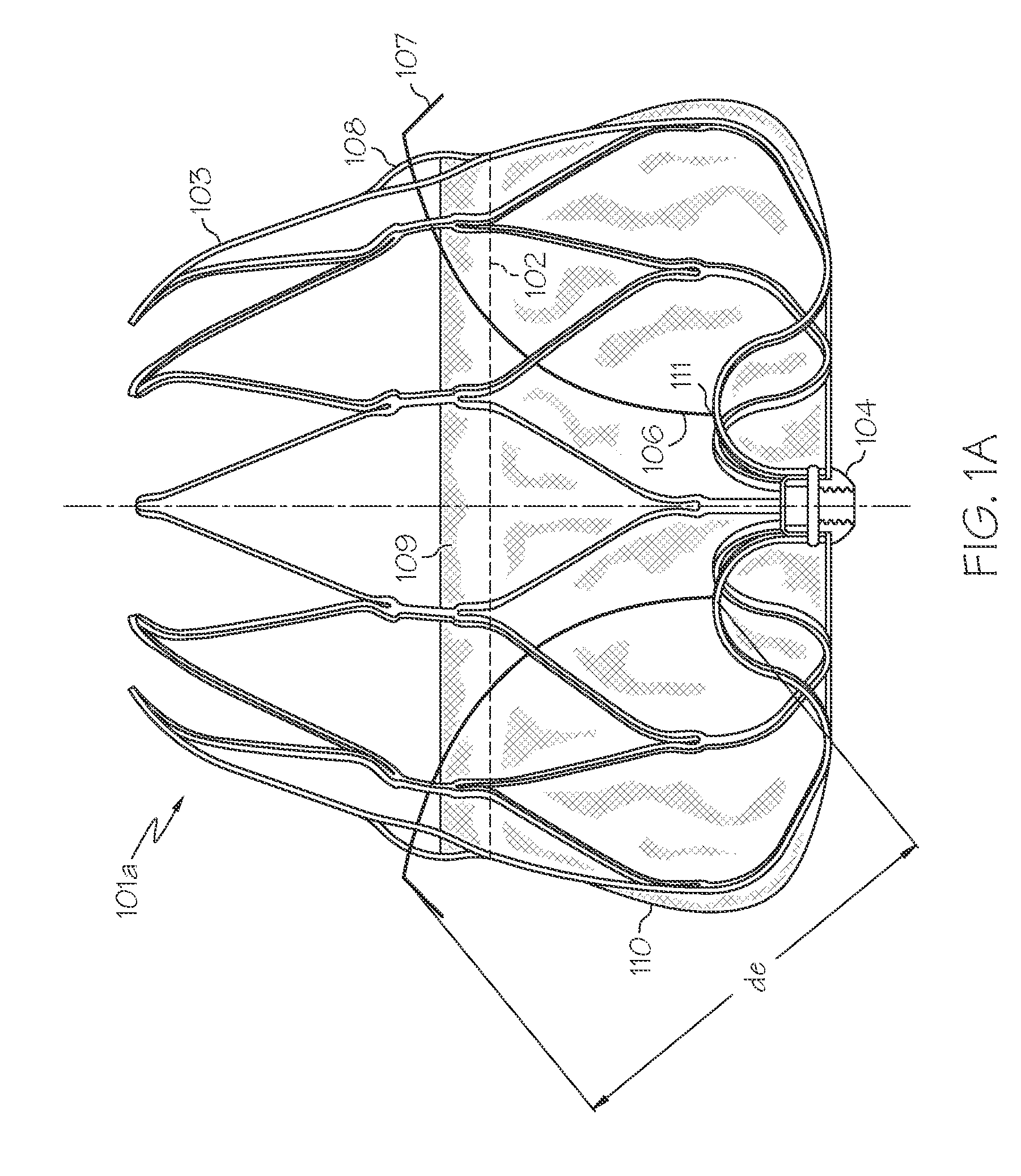
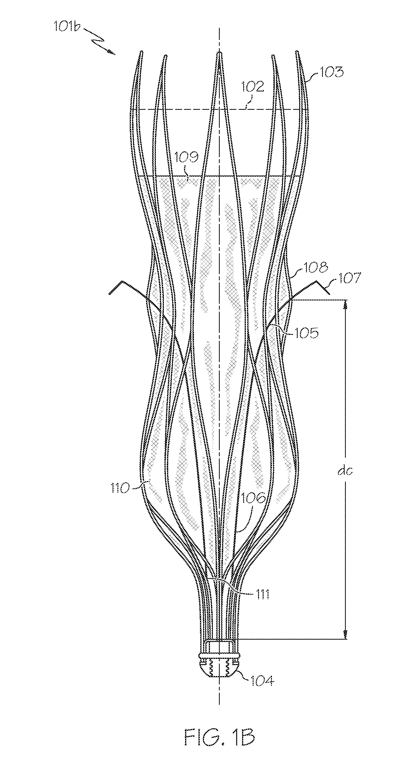
[0033]FIG. 1 depicts on potential embodiment of the present invention comprising a main body structure 101. As shown in FIGS. 1A and 1B, the embodiment depicted has an expanded state 101a, FIG. 1A, and a constrained state 101b, FIG. 1B. The outer perimeter, shown by dashed line 102, of main body 101 is larger in the expanded stated than when in the constrained state. Main body 101 is formed from a plurality of ribs 103 extending radially outwards from nexus 104 and defining an interior 109. A plurality of fixation struts 105 are within main body 101....


PUM


Abstract

An implantable medical device having barbs reducing in height and/or changing angle as the implantable medical device transitions for an expanded state to a constrained state is disclosed which may lessen the risk of injury associated with the removal and/or repositioning of a deployed device. Within the main body of the device may be positioned a plurality of fixation struts having an end secured to the main body and a barb end exiting the main body at a point of egress and extending radially outwards from the main body. The fixation struts may be secured to the main body such that the distance between the point of attachment of the secured end of a fixation strut and the respective point of egress from the main body its free barb forming end is greater in the constrained than expanded state.

Description

CROSS-REFERENCE TO RELATED APPLICATIONS[0001]This Application claims the benefit of and priority to U.S. Provisional Application No. 61 / 700,221, filed Sep. 12, 2012, the entire contents of which are herein incorporated by reference.BACKGROUND OF THE INVENTION[0002]This invention relates to fixation anchors that may be incorporated into the structure of an occlusion device or vascular filter.[0003]Medical devices implantable within the vasculature are often used to mitigate against blood clots, deep venous thrombosis, and / or pulmonary emboli when anticoagulation therapy is contraindicated. For example, a pregnant woman afflicted with atrial fibrillation may be implanted with a left atrial appendage occlusion device rather than prescribed anticoagulants. Once in place, the device provides scaffolding over which a tissue plug isolating the left atrial appendage may be formed. As another example, an elderly patient having just undergone a major surgery may be fitted with an inferior ven...

Claims


Application Information

Patent Timeline
IPC IPC(8): A61F2/01
CPCA61F2/01A61B17/12122A61B17/12172A61B17/12177A61F2220/0016A61B2017/00867A61F2/0105
Inventor TISCHLER, BRIAN JOSEPHPEIFFER, DENNIS A.
Owner BOSTON SCI SCIMED INC
Why Eureka
Try Eureka