
Building Wall Assembly

Inactive Publication Date: 2014-03-20
MERCADO FAUSTINO V
View PDF6 Cites 13 Cited by
  • Summary
  • Abstract
  • Description
  • Claims
  • Application Information

AI Technical Summary

Benefits of technology

The invention is a low-cost construction method using foamed polymeric panels and partially embedded wooden studs. This allows for easy manufacturing and installation. The simple profile of the studs allows for easy sliding into the panel and provides a utility space for running plumbing and electrical lines. Structural sheathing is also directly attached to the studs for increased strength and an accessible utility space. Overall, the invention provides a cost-effective and efficient way to construct buildings.

Problems solved by technology

No means are provided on conventional polymeric foamed panels for improving the insulation in the space between adjacent ones of the studs.
Due to the complex cross section of the studs however, the construction of the panels to surround the studs is complex and expensive.
Furthermore, the space between the studs is typically filled with material when the studs are imbedded into the foamed material such that there is little or no access for running utilities such as electrical or water lines in the spaces between the studs as desired in conventional construction techniques.
In one embodiment of U.S. Pat. No. 5,943,775, the studs are only partially imbedded into the insulating foam panels, however doing so requires a costly and complex manufacturing process to form mating channels into which the studs must be vertically slidable to assemble.
Accordingly, the assembly is also awkward and inefficient.
Furthermore no clear means are disclosed for securing structural sheathing to the studs as required according to many building codes.
In each instance, the studs are fully embedded in the foam material however, such that the foam completely fills the space between adjacent studs so that there is no ready access for running utilities such as water and electrical lines.

Method used


Image

  • Building Wall Assembly
  • Building Wall Assembly
  • Building Wall Assembly

Examples


Embodiment Construction

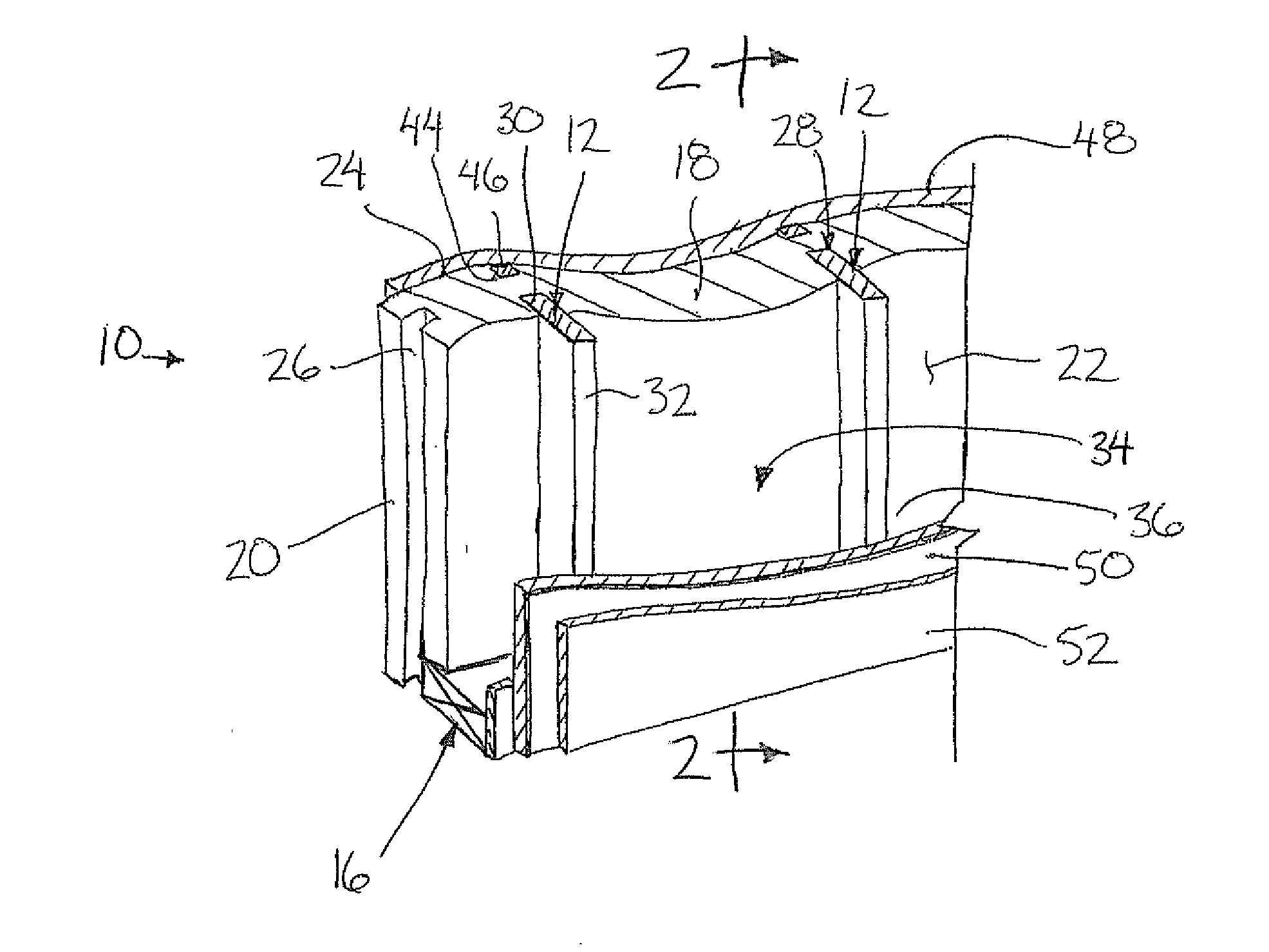
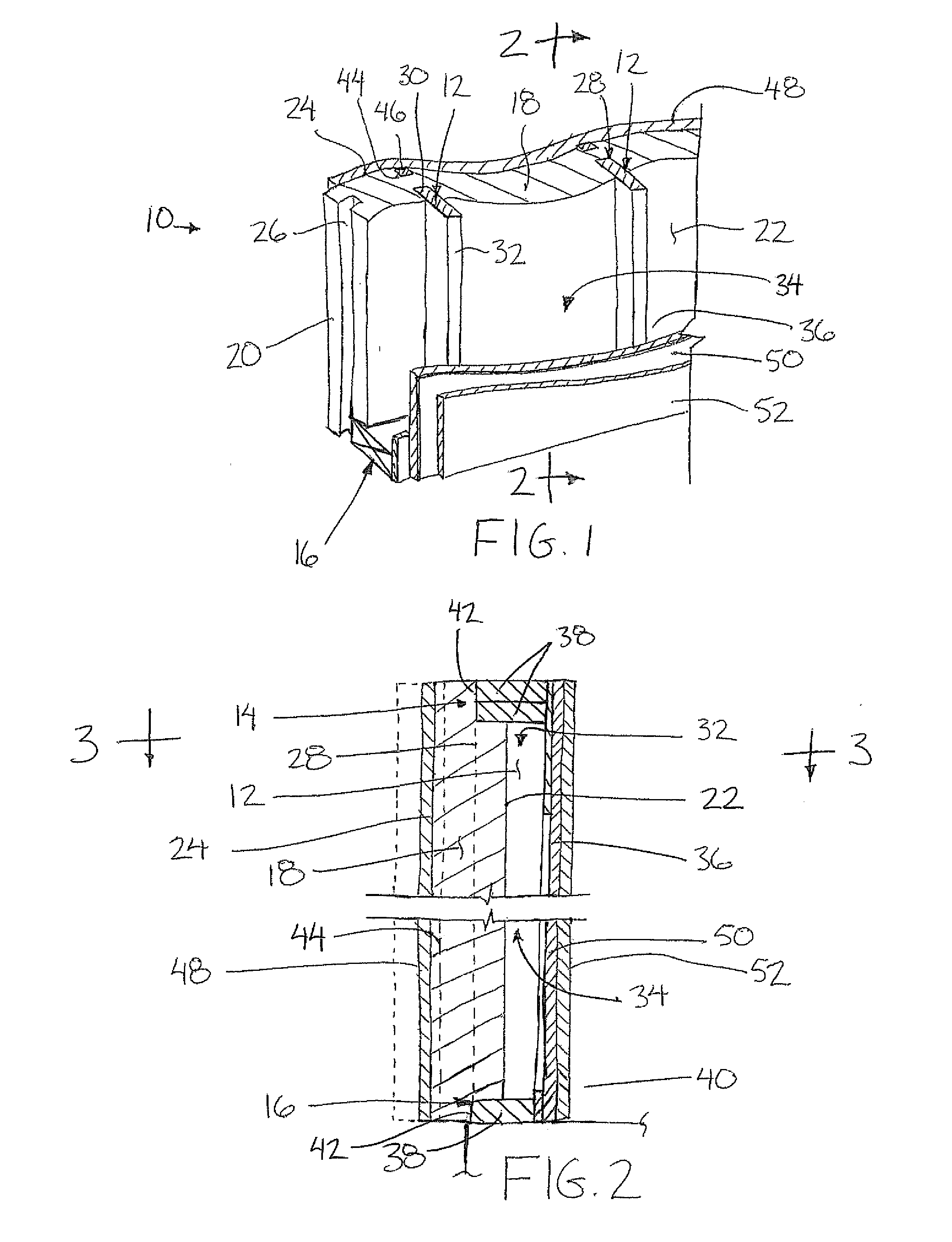
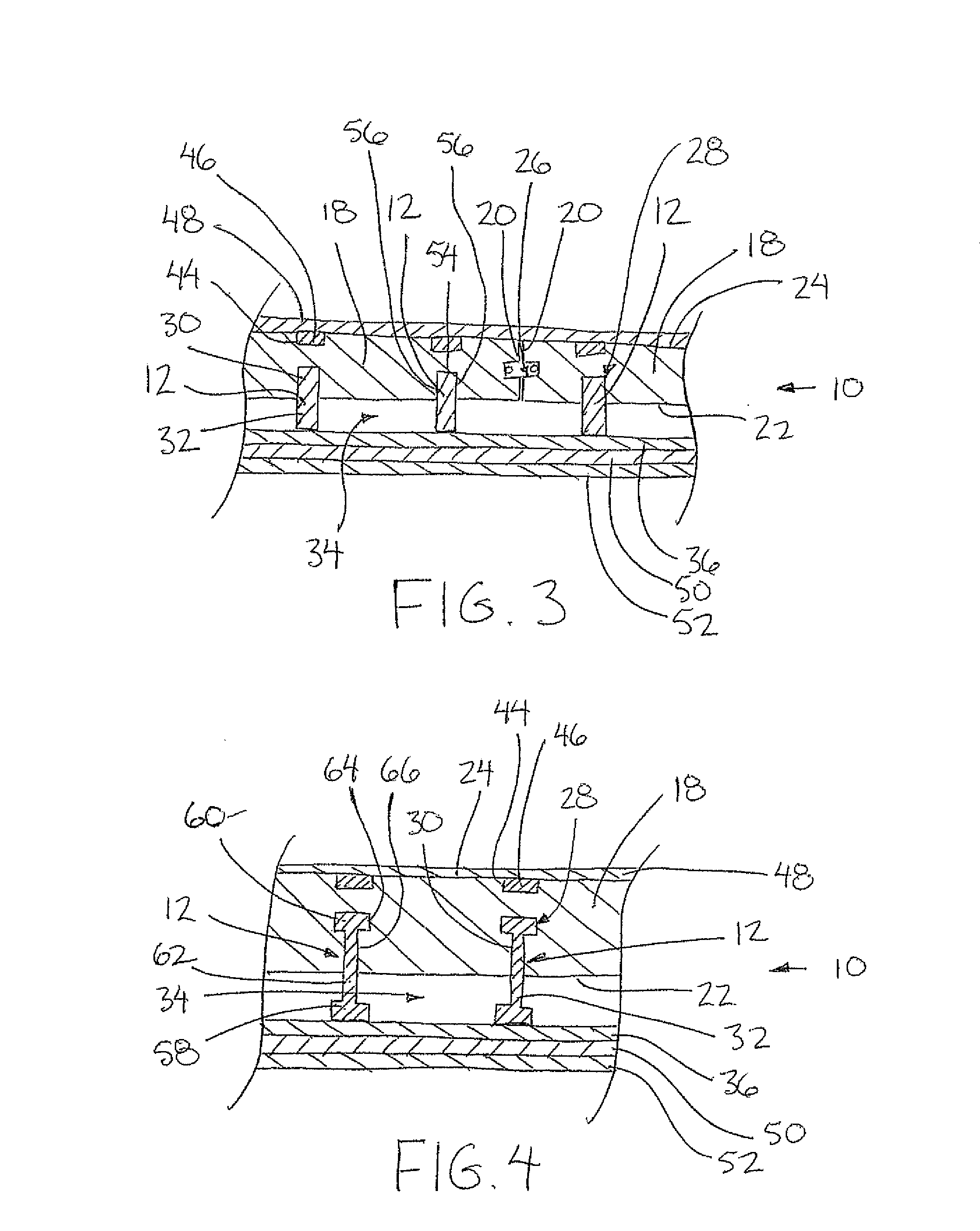
[0047]Referring to the accompanying figures there is illustrated a building wall assembly generally indicated by reference numeral 10. The wall assembly 10 is suited for use as a wall in various buildings including commercial and residential applications.

[0048]The wall assembly 10 includes a plurality of studs 12 which span vertically between a header member 14 at a top end of the wall and a footer member 16 at the bottom end of the wall. The header and footer member extend in the longitudinal direction along the wall so as to span across all of the studs of the wall which are evenly spaced apart in the longitudinal direction by a standard spacing, for example 16 inches between centers.

[0049]The studs may comprise a wooden stud of rectangular cross section as shown in FIGS. 1 through 3, a wooden I-beam construction as shown in FIG. 4, or a metal stud of generally rectangular U-shaped configuration as shown in FIGS. 5 and 6.

[0050]The wall assembly further includes a plurality of insu...


PUM


Abstract

A building wall assembly includes a panel of foamed polymeric material and studs received in channels at the inner side of the panel such that only an outer portion of the stud fits in the channel and an inner portion of the stud projects from the panel to define a utility space at the inside of the panel. Wooden structural sheathing material is joined across an upper portion of the studs at the inner side. Auxiliary sheathing material, for example concrete board, spans the outside of the panel in connection with strapping members recessed into strapping channels at the outside of the panel in which each strapping member is fastened through the panel to a respective stud. The studs may be wooden. Alternatively metals studs are used with utilities apertures therein so that spray foamed material can be connected between opposing sides of the stud channel through the utility apertures.

Description

FIELD OF THE INVENTION[0001]The present invention relates to a wall assembly for use as an insulated wall in a building, and more particular the present invention relates to a wall assembly including studs which are recessed into rigid panels of foamed polymeric insulating material.BACKGROUND[0002]Various examples of wall assemblies for buildings are known in the prior art for being easy to assemble and for providing optimal insulation to the completed building. One common form of insulation is the use of a polymeric foamed panel. As described in U.S. Pat. No. 6,421,972 by Dalphond et al, insulating panels of this type may be used to form a continuous outer layer along an outer side of studs used in a structural wall to provide a thermal break on one side of the studs. No means are provided on conventional polymeric foamed panels for improving the insulation in the space between adjacent ones of the studs.[0003]U.S. Pat. No. 5,265,389 by Mazzone et al and U.S. Pat. No. 5,943,775 by ...

Claims


Application Information

Patent Timeline
IPC IPC(8): E04B2/26E04B1/62
CPCE04C2/386E04C2/521E04B2/58E04B2/707E04B2/7412
Inventor MERCADO, FAUSTINO V.
Owner MERCADO FAUSTINO V
Features
  • Generate Ideas
  • Intellectual Property
  • Life Sciences
  • Materials
  • Tech Scout
  • Unparalleled Data Quality
  • Higher Quality Content
  • 60% Fewer Hallucinations
Learn More