Flexible unbonded pipe

a flexible, unbonded technology, applied in the direction of drilling pipes, drilling rods, mechanical equipment, etc., can solve the problems of high inter-laminar crushing forces, and achieve the effect of low weight and desired strength

Inactive Publication Date: 2014-03-20
NAT OILWELL VARCO DENMARK
View PDF2 Cites 11 Cited by
  • Summary
  • Abstract
  • Description
  • Claims
  • Application Information

AI Technical Summary

Benefits of technology

[0013]The object of the invention is to provide a flexible pipe which pipe can be provided with desirable low weight in long length and with a desired strength against bursting of the inner sealing sheath. Furthermore it is an object that the pipe can be manufactured in a cost effective manner.

Problems solved by technology

An identified but until now unsolved problem relating to prior art fiber reinforced pipes is that virtually any severe mechanical load on such flexible pipe will result in high inter-laminar crushing forces.

Method used


Image

  • Flexible unbonded pipe
  • Flexible unbonded pipe
  • Flexible unbonded pipe

Examples


Embodiment Construction

75°65°40°Example B75°65°10°Example C85°55°30°Example D80°50°20°Example E60°45°10°Example F55°30° 5°

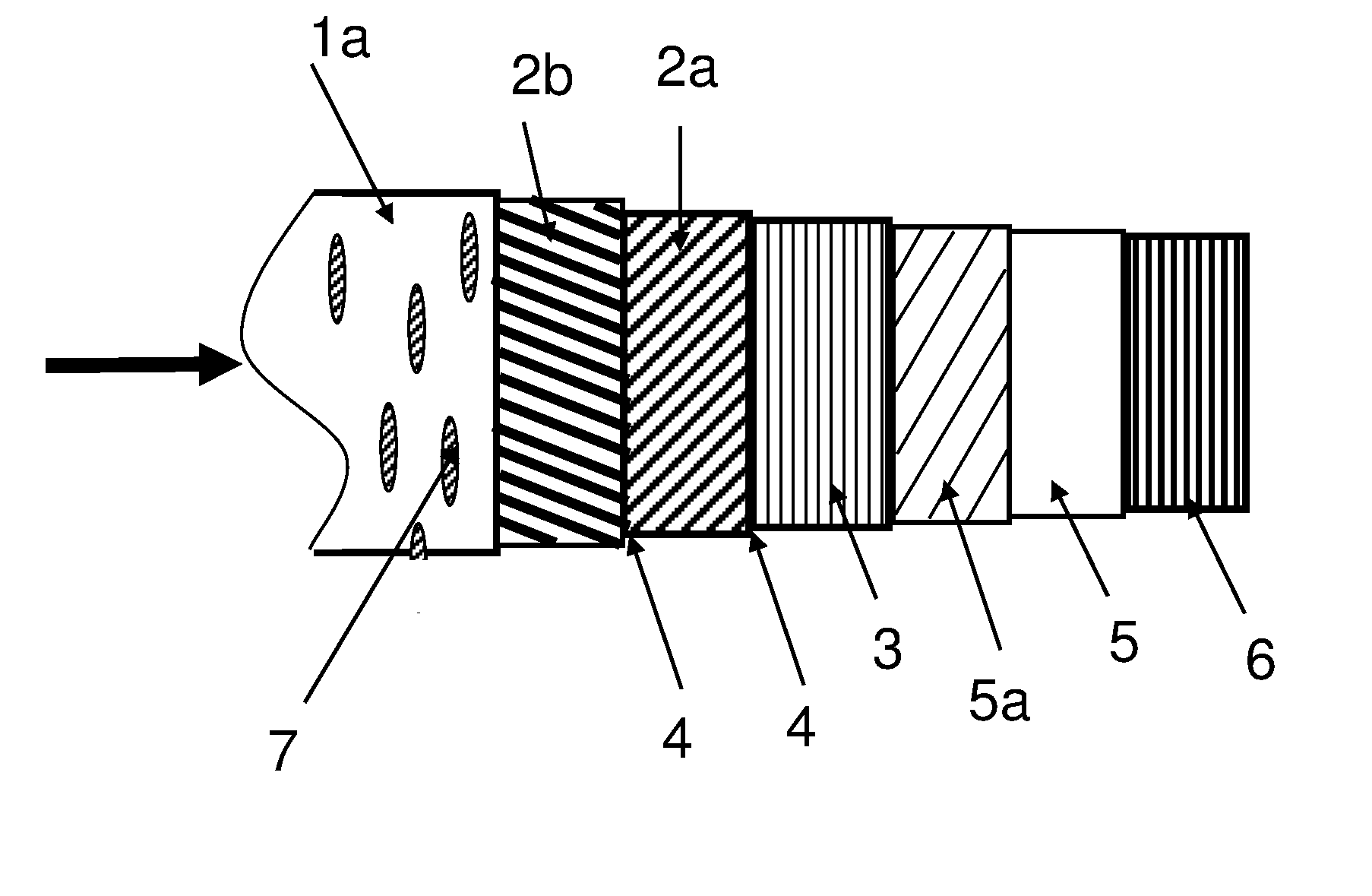
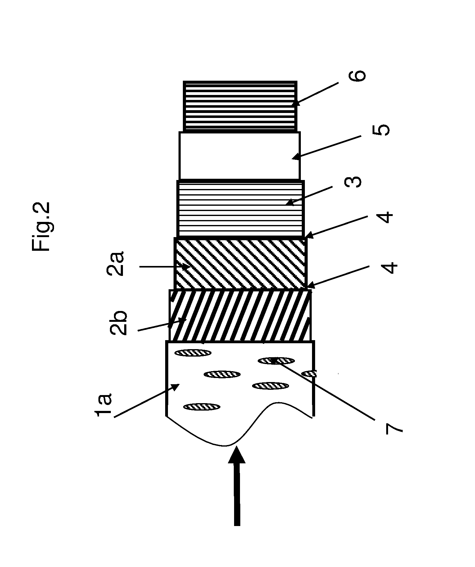
[0125]FIG. 2 shows a schematic side view of a second flexible unbonded pipe of the invention. The second unbonded flexible pipe of the invention differs from the pipe shown in FIG. 1, in that the outer sheath 1a is an extruded polymer layer which is perforated with the perforations 7 such that the outer sheath is an outer mechanical protection layer which is permeable to liquid.

[0126]FIG. 3 shows a schematic side view of a third flexible unbonded pipe of the invention. The third unbonded flexible pipe of the invention differs from the pipe shown in FIG. 2, in that the pipe comprises a wound film layer 5a which is wound onto the inner sealing sheath 5 and the anti-creep layer 3 is placed in direct contact with the wound film layer 5a.

[0127]FIG. 4 shows an offshore system comprising an unbonded flexible pipe 12 of the invention. The dotted line 10 indicates the sea surface. The offshore...


PUM

PropertyMeasurementUnit
angleaaaaaaaaaa
thicknessaaaaaaaaaa
αaaaaaaaaaa

Abstract

The invention relates to a flexible unbonded pipe for sub sea fluid transfer. The pipe comprises an inner sealing sheath defining a bore and a centre axis. Inside the inner sealing sheath the pipe comprises a carcass. The pipe further comprises a pair of reinforcement layers consisting essentially of helically wound elongate armoring elements of fiber reinforced polymer material. The elongate armoring elements of the innermost of the pair of reinforcement layers are wound in a first winding direction with an angle α to the centre axis, and the elongate armoring elements of the outermost of the pair of reinforcement layers are wound in a second winding direction with an angle β to the centre axis, wherein α≧βfπ / 2, α is about 65° or less. The pipe preferably comprises an anti-creep layer placed between the inner sealing sheath and the innermost of the pair of reinforcement layers.

Description

TECHNICAL FIELD[0001]The present invention concerns a flexible unbonded pipe for sub sea fluid transfer, for example for transporting water or aggressive fluids, such a petrochemical products, e.g. from a production well to a sea surface installation.BACKGROUND ART[0002]Flexible unbonded pipes of the present type are for example described in the standard “Recommended Practice for Flexible Pipe”, ANSI / API 17 B, fourth Edition, July 2008, and the standard “Specification for Ubonded Flexible Pipe”, ANSI / API 17J, Third edition, July 2008. Such pipes usually comprise an inner liner also often called an inner sealing sheath or an inner sheath, which forms a barrier against the outflow of the fluid which is conveyed in the bore of the pipe, and one or more armoring layers. In general flexible pipes are expected to have a lifetime of 20 years in operation.[0003]Examples of unbonded flexible pipes are e.g. disclosed in WO0161232A1, U.S. Pat. No. 6,123,114 and U.S. Pat. No. 6,085,799.[0004]Th...

Claims


Application Information

Patent Timeline
Patent Type & Authority Applications(United States)
IPC IPC(8): F16L11/08F16L11/18
CPCF16L11/082F16L11/18E21B17/015F16L11/083
Inventor GLEJBOL, KRISTIAN
Owner NAT OILWELL VARCO DENMARK
Why Eureka
Try Eureka