Tools

a technology of tools and sledgehammers, applied in the field of tools, can solve the problems of ineffective posthole borers, ineffective posthole borers, and inability to operate, so as to increase the overall usefulness and impact the strength of sledgehammers, reduce the jarring effect associated, and increase the overall amount of momentum

Inactive Publication Date: 2014-03-20
BELSEY MAXWELL DEREK +1
View PDF2 Cites 4 Cited by
  • Summary
  • Abstract
  • Description
  • Claims
  • Application Information

AI Technical Summary

Benefits of technology

[0036]Preferably however, the handle may be made from a substantially strong and / or heavy material, for example a metal such as steel. Being made from such a material imparts strength to the tool during use, and furthermore, the significant weight of such a material provides the tool with substantial momentum during use of the tool.
[0075]In another embodiment of the present invention, the impact portion of the tool may be releasably attachable to the handle, whereby a number of different impact portions may be attached to the handle and used as or when required or desired. For example, an impact portion in the form of an axe head (with a cutting surface) may be attached to the handle and the tool used to dig a hole and / or cut through ground impediments such as tree roots. Once the hole has been dug, and a post placed into the hole, the axe head may be removed and a compacting head attached to the handle so that the tool may be used to compact the ground or soil around the post.

Problems solved by technology

However, disadvantages or limitations associated with the use of posthole borers include the following:1. They are less effective, and also potentially dangerous, when digging holes in ground that has obstacles or impediments such as tree roots, stones, rocks, concrete, scoria, reinforcing mesh, frozen ground, and the like.
For example, unexpectedly, hitting a rock could damage the posthole borer and / or injure the person operating it.2. Posthole borers are only able to dig holes of a certain size, that is, holes of the same diameter as the auger.
Hence, in situations where different-sized holes must be dug, posthole borers may be ineffective, and some holes may have to be dug by hand.
Furthermore, posthole borers often dig holes that are much larger than the size of the posts to be placed in the hole, thus requiring more work to secure the post in place (for example, by concreting or by adding and / or compacting soil around the post).3. Posthole borers are heavy and cumbersome, and therefore difficult to transport.
Furthermore, they may be ineffective when digging holes in confined spaces, for example, next to a wall.4. The cost of purchasing and / or hiring and / or running a posthole borer may be prohibitive.
As a result of the above disadvantages, many fencing contractors (and especially those primarily working on domestic house sites) do not use posthole borers, and instead utilise hand tools for digging holes.
However, spades have limitations when digging in ground that has impediments such as tree roots, which is a very common occurrence when working on house sites.
An axe may be utilised to attempt to break through tree roots, however there is not usually enough room to properly swing the axe.
This is time consuming, and therefore costly in situations where a contractor has quoted a fixed price for a job.
Spades (and axes) also have limitations when digging in ground that has obstacles such as stones, rocks, concrete, scoria, reinforcing mesh, or even just particularly hard ground, or ground that has a high clay content.
In such digging situations the time taken to dig a hole may be substantial, which again may be costly in situations where a contractor has quoted a fixed price for a job.
Furthermore, in order to clear the impediments and dig the hole, the contractor may misuse tools, that is, by using them in a style or manner that they were not designed for.
Such misuse of tools may result in injury to the user and / or damage to the tools.
Moreover, when digging holes by hand, there is always the possibility of injury or jarring to the contractor, for example when he / she unexpectedly hits a tree root or rock with a spade.
The use of any hand held impact tool over time tends to tire the user, both through the general exertion associated with using the tool, and also through the user being subjected to the jarring forces associated with repeated impacts of the tool.

Method used


Image

  • Tools
  • Tools
  • Tools

Examples


Embodiment Construction

[0078]The description of a preferred form of the invention to be provided herein, with reference to the accompanying drawings, is given purely by way of example and is not to be taken in any way as limiting the scope or extent of the invention.

DRAWINGS

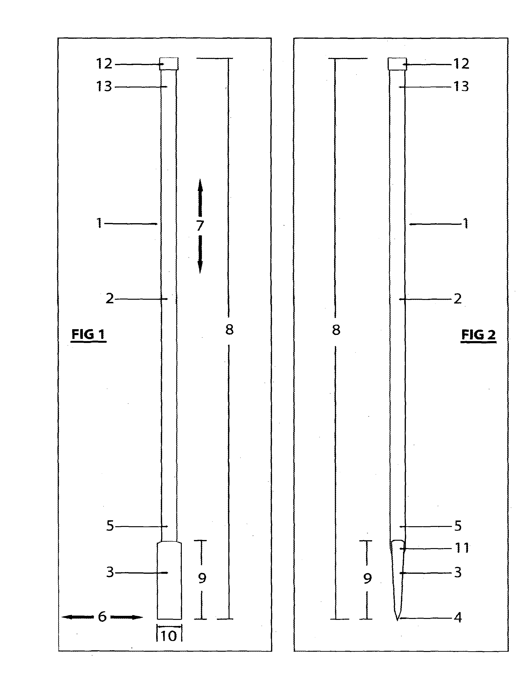
[0079]FIG. 1: is a front view of one possible embodiment of the present invention,

[0080]FIG. 2: is a side view of the embodiment illustrated in FIG. 1,

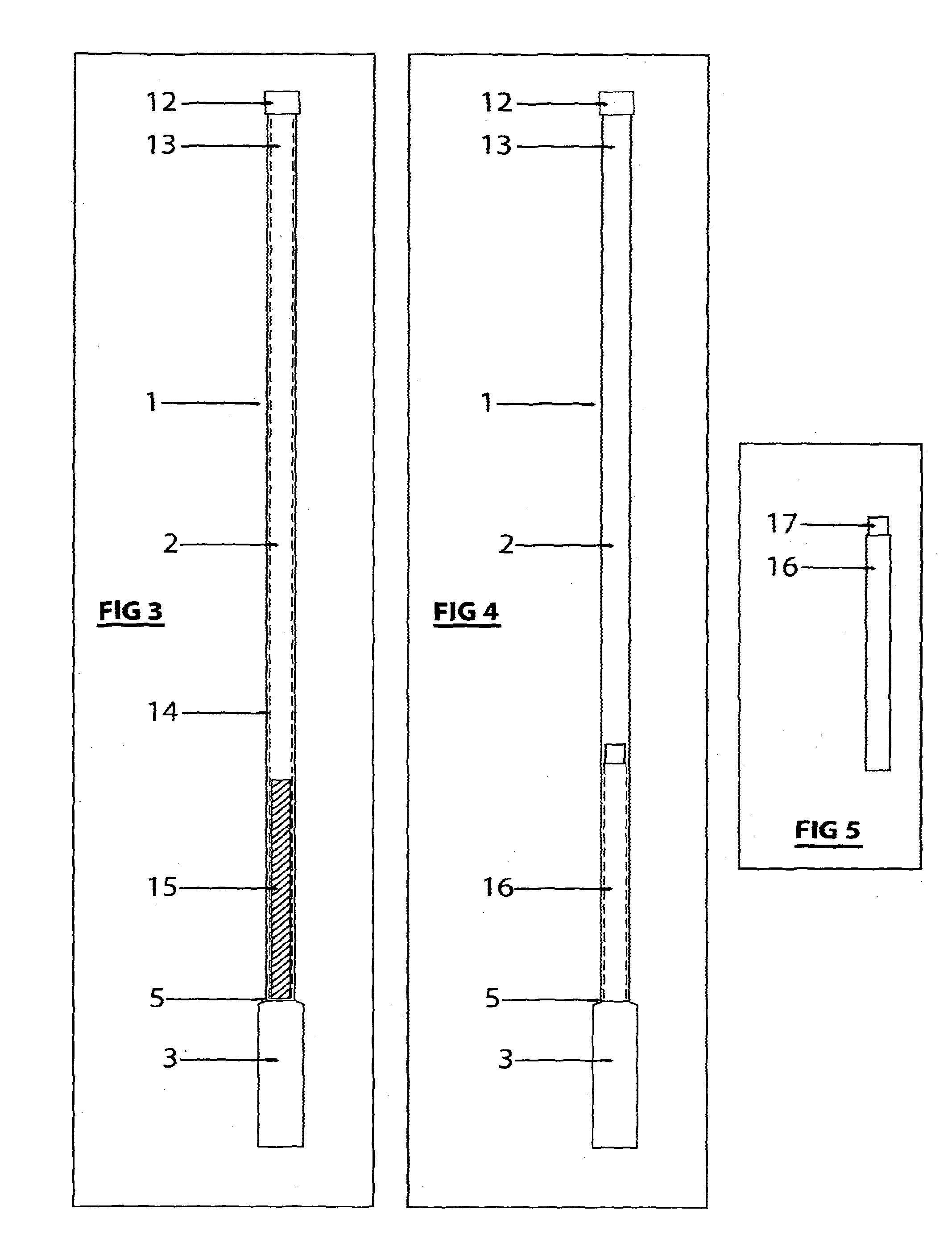
[0081]FIG. 3: is a cut away view of the embodiment show in FIG. 1,

[0082]FIG. 4: is a cut away view of a different possible embodiment of the present invention, and

[0083]FIG. 5: is a view of a container used for housing a moveable material, as illustrated in FIG. 4.

DESCRIPTION OF PREFERRED EMBODIMENTS

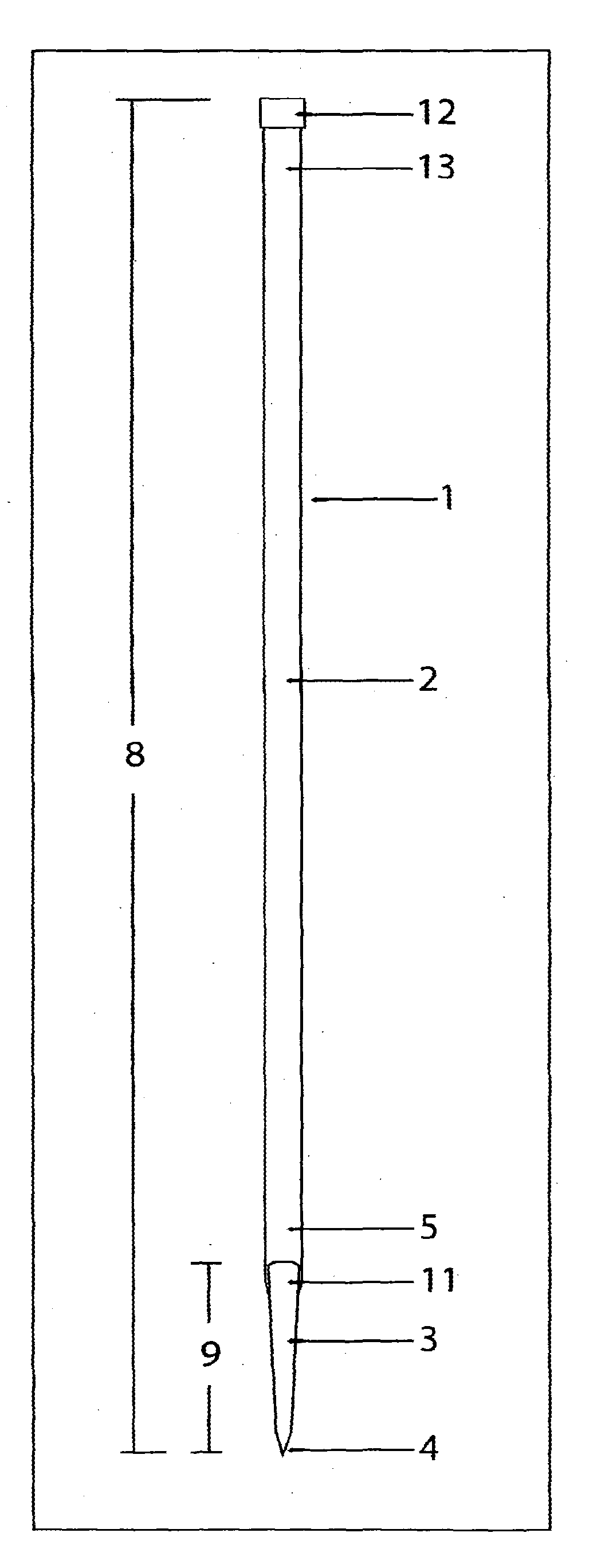
[0084]Having regard to FIGS. 1 and 2, there is shown an impact tool generally indicated by arrow 1.

[0085]The tool has a handle 2, and an impact portion 3, with a cutting surface 4. The impact portion 3 is fitted to a first end 5 of the handle 2. As can be seen from FIG. 1, the arrangement and...


PUM


Abstract

This invention relates to an impact tool. The impact tool includes a handle, and the handle includes a hollow portion. The impact tool also includes an impact portion for impacting with a surface or object, with the impact portion being located at one or both ends of the handle. The impact tool further includes a moveable material, which may be housed within the hollow portion of the handle. The moveable material is adapted or able to move along the hollow portion of the handle during use of the impact tool. The moveable material may serve to increase the momentum associated with the use of the impact tool and / or to reduce the jarring effect associated with the use of the impact tool.

Description

CROSS REFERENCE TO RELATED APPLICATIONS[0001]This application is a continuation of application Ser. No. 13 / 062,626 filed on Mar. 7, 2011, which is a National Stage of PCT / NZ2009 / 000185 filed on Sep. 4, 2009, which claims foreign priority to New Zealand Application No. 571026 filed on Sep. 5, 2008. The entire contents of each of the above applications are hereby incorporated by reference.FIELD[0002]This invention relates to improvements in relation to tools. The invention may be particularly suitable for use in relation to hand tools which may be used as impact tools, and the invention will therefore predominantly be described in relation to such use.BACKGROUND[0003]A major part of the work of a contractor, such as a fencing contractor, is the digging of holes in the ground, for example, for housing fence posts.[0004]In situations where many holes must be dug and / or where the ground is mostly free of any impediments (for example, when building a fence on farmland) a mechanical postho...

Claims


Application Information

Patent Timeline
Patent Type & Authority Applications(United States)
IPC IPC(8): A01B1/00
CPCA01B1/00B25D1/00B25D2250/241A01C5/02B25F1/006B25G1/04B25G1/10B25G3/16B27L7/005B25D1/12B25D7/00
Inventor BELSEY, MAXWELL DEREKGRAY, TERRY JOHN
Owner BELSEY MAXWELL DEREK
Why Eureka
Try Eureka