Vapor chamber and method of manufacturing the same

a technology of vapor chamber and manufacturing method, which is applied in the field of vapor chamber, can solve the problems of vapor chamber, vapor chamber, appearance or appearance of poor, and achieve the effect of keeping the working environment of the production line clean

Inactive Publication Date: 2014-03-20
WANG TZU +3
View PDF0 Cites 12 Cited by
  • Summary
  • Abstract
  • Description
  • Claims
  • Application Information

AI Technical Summary

Benefits of technology

[0012]Comparing to the prior art, the present invention has the following effects. The vapor chamber of the present invention has a lower shell and an upper shell, and an annular slot formed on the periphery of the top plate of the upper shell. When the upper shell covers on the lower shell, a solder accommodating space is formed between the annular slot of the upper shell and the lower side plate of the lower shell. By this constitution, the solder is dropped in the solder accommodating space from the upp

Problems solved by technology

However, the vapor chamber made in this way has some disadvantages as following.
The periphery of the vapor chamber is not in a flat state and the appearance or looks thereof is not good.
Therefore, the solder tends to

Method used


Image

  • Vapor chamber and method of manufacturing the same
  • Vapor chamber and method of manufacturing the same
  • Vapor chamber and method of manufacturing the same

Examples


Embodiment Construction

[0022]In cooperation with attached drawings, the technical contents and detailed description of the invention are described thereinafter according to a number of preferable embodiments, being not used to limit its executing scope. Any equivalent variation and modification made according to appended claims is all covered by the claims claimed by the present invention.

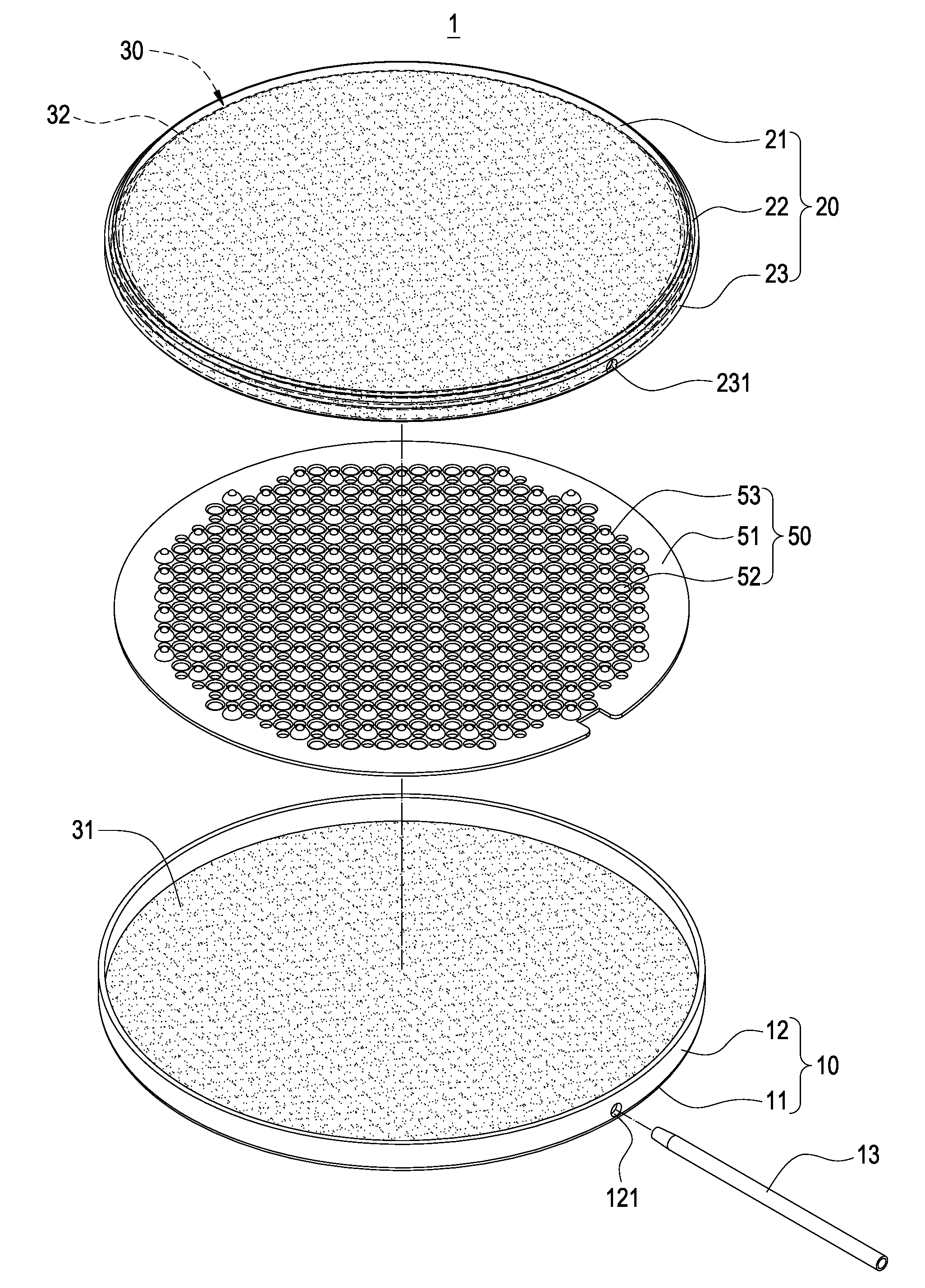
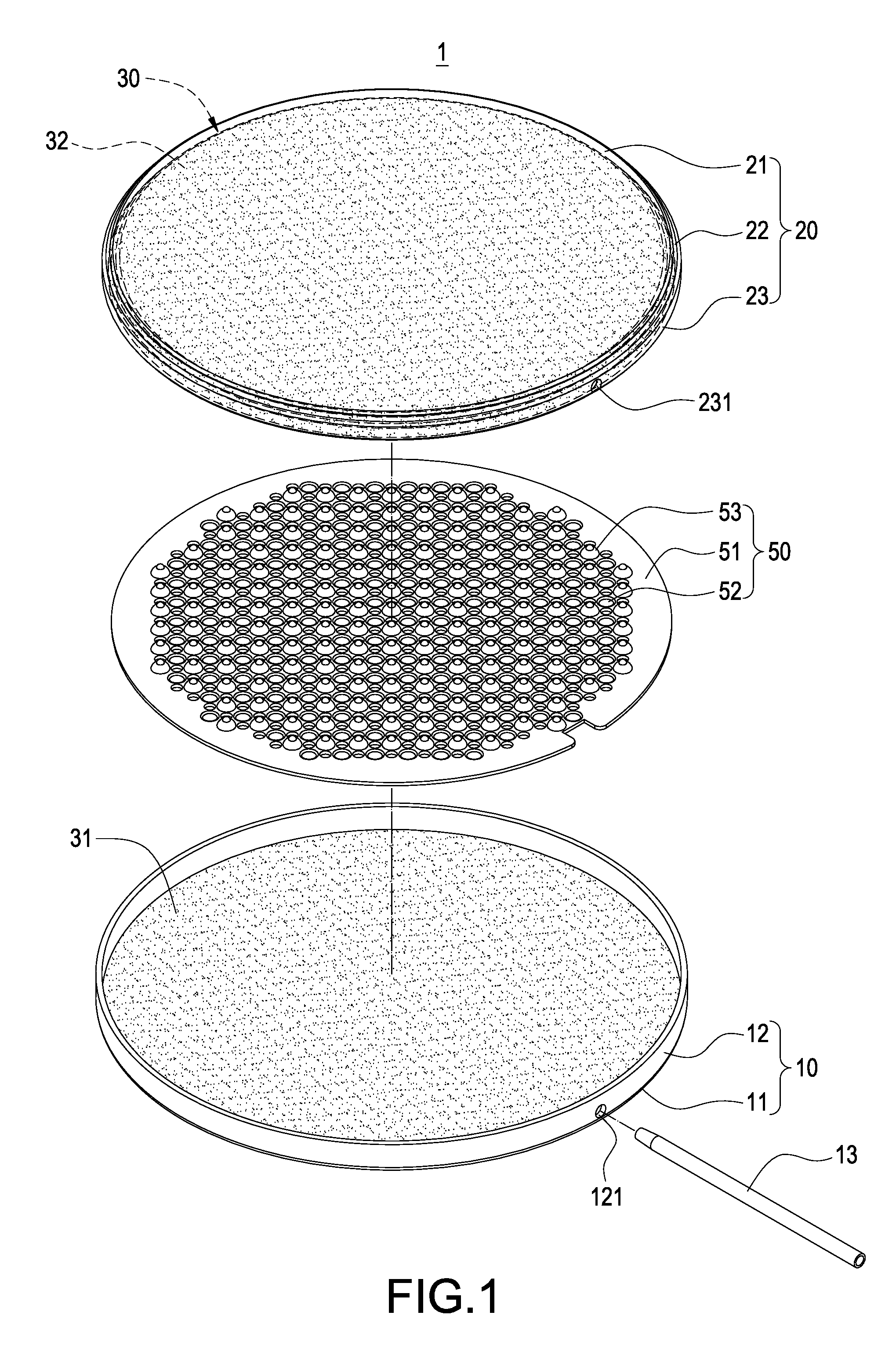
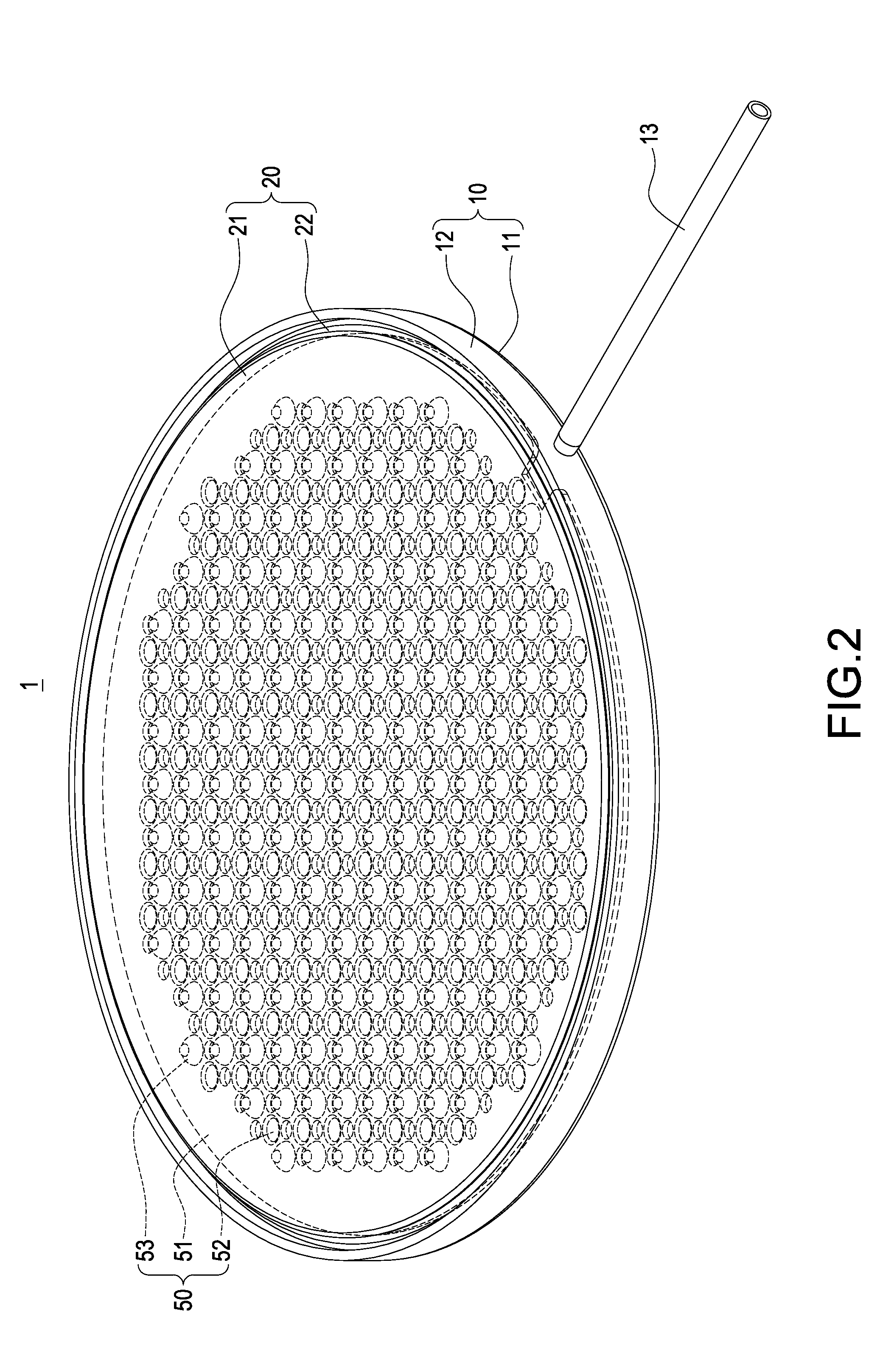
[0023]Please refer to FIG. 1 to FIG. 5, the invention provides a vapor chamber and method of manufacturing the same. The vapor chamber 1 of the present invention includes a lower shell 10, an upper shell 20, a wick structure 30, a working fluid 40, and a supporting structure 50.

[0024]The lower shell 10 is in a disc shape generally, and it can be made of metal or ceramic material. The lower shell 10 has a bottom plate 11 and a lower side plate 12 extended from the periphery of the bottom plate 11. The lower side plate 12 has a degassing hole 121 for penetrating a degassing tube 13. Beside, a lower capillary wick 31 is sin...


PUM


Abstract

A vapor chamber and method of manufacturing the same are disclosed. The vapor chamber includes a lower shell, an upper shell, a wick structure and a working fluid. The lower shell has a bottom plate and a lower side plate extended from a periphery of the bottom plate. The upper shell has a top plate, an annular slot formed on the outer edge of the top plate, and an upper side plate extended from a periphery of the annular slot. The upper shell covers the lower shell so that the upper side plate abuts against the lower side plate, and a solder accommodating space is formed between the annular slot and the lower side plate.

Description

BACKGROUND OF THE INVENTION[0001]1. Field of the Invention[0002]The present invention generally relates to a vapor chamber and method of manufacturing the same, in particular to a vapor chamber with a solder accommodating space and method of manufacturing the same.[0003]2. Description of Prior Art[0004]As progress continues to be made in technology and compactness to be required of electronic productions, many kinds of vapor chambers are developed to dissipate heat for heating electronic components.[0005]Currently, a vapor chamber is made by coupling a lower shell and an upper shell, and then the periphery of the lower shell and the upper shell will be aligned and pressed. Finally, the pressed periphery is sealed with solder.[0006]However, the vapor chamber made in this way has some disadvantages as following. Firstly, the periphery of the vapor chamber will form a flange produced from soldering. The periphery of the vapor chamber is not in a flat state and the appearance or looks t...

Claims


Application Information

Patent Timeline
IPC IPC(8): A01G27/00B23P11/00
CPCG06F1/20H05K7/20336Y10T137/0402
Inventor WANG, CHIN-WEN
Owner WANG TZU
Why Eureka
Try Eureka